Thermostat Calls for Heat but the HVAC Never Starts
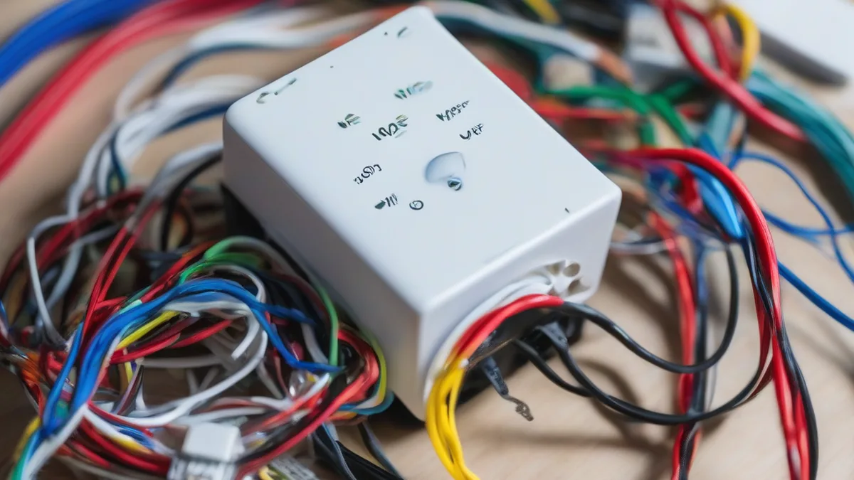
Quick Verdict: Smart Thermostat HVAC Control Issues
If your smart thermostat isn’t reliably engaging your heating or cooling system, the most common culprits are insufficient power (often related to the ‘C-wire‘), incorrect wiring, or a blown fuse in your HVAC system‘s control board. Begin by safely powering down your HVAC, visually inspecting all wiring connections at both the thermostat and the furnace/air handler, and then verifying voltage with a multimeter. Many modern smart thermostats require a continuous 24V AC supply, which older systems might not provide without modifications like a dedicated C-wire or a power extender kit.
Upgrading to a smart thermostat often ends the same way: the thermostat works, and the heating or cooling system does not respond. The promise of intelligent climate control can quickly turn into a headache when your smart device fails to communicate effectively with your HVAC system. This isn’t just a minor inconvenience; it can lead to uncomfortable living conditions, energy waste, and even potential damage to your HVAC components if ignored. This comprehensive guide will walk you through the precise steps to diagnose and resolve these critical control failures, ensuring your smart thermostat and HVAC system work in perfect harmony.
Understanding the Low-Voltage Language of Your HVAC System
At its core, your smart thermostat communicates with your HVAC system using low-voltage (typically 24V AC) electrical signals. These signals activate relays on your furnace or air handler’s control board, telling it to turn on the fan, engage the heat, or run the compressor for cooling. When these signals are interrupted, misinterpreted, or simply not strong enough, your HVAC system becomes unresponsive.
The Critical Role of the C-Wire (Common Wire)
Many older thermostats were ‘power-stealing’ devices, drawing minimal power directly from the R (Red, 24V AC hot) and W (White, heat) wires. This was sufficient for simple mechanical or battery-powered thermostats. However, smart thermostats, with their Wi-Fi radios, backlit displays, and advanced processors, require a continuous and stable power supply. This is where the ‘C-wire’ (Common wire) becomes indispensable. The C-wire provides a continuous return path for the 24V AC power, ensuring your thermostat always has enough juice without ‘stealing’ power that could cause intermittent operation or ‘chatter’ in your HVAC relays.
Without a C-wire, some smart thermostats attempt to ‘power steal’ by briefly cycling the heating or cooling circuit, which can lead to:
- Intermittent operation: Your system might turn on and off erratically.
- Short cycling: The system runs for very brief periods, inefficiently.
- Relay chatter: The HVAC control board’s relays rapidly switch on and off, potentially damaging them.
- Battery drain: If your smart thermostat has a battery, it will drain quickly trying to compensate for insufficient wired power.
- No operation at all: The most frustrating outcome, where the thermostat simply cannot command the system.
Common Wiring Mistakes and Misconfigurations
Even with a C-wire, incorrect wiring is a frequent cause of control issues. Each terminal on your thermostat corresponds to a specific function in your HVAC system. A misplaced wire can prevent a function from engaging or even cause a short circuit. For instance, connecting the ‘Y’ (Cooling) wire to the ‘W’ (Heating) terminal would mean your thermostat tries to activate cooling when you request heat, and vice-versa.
HVAC System Compatibility
While most smart thermostats are designed for conventional single-stage heating and cooling systems, complications can arise with multi-stage systems (e.g., W1, W2 for two-stage heating), heat pumps (O/B, Aux, E terminals), or systems with humidifiers/dehumidifiers (accessory terminals like HUM, DEHUM). Ensuring your smart thermostat supports your specific HVAC configuration and is correctly configured within its settings is crucial.
Here’s a breakdown of common HVAC wiring terminals and their functions:
| Terminal Label | Wire Color (Typical) | Function | Expected Voltage (to C-wire) |
|---|---|---|---|
| R (Rh/Rc) | Red | 24V AC Hot (Power) | Always ~24V AC |
| C (Common) | Blue/Black | 24V AC Common (Return) | 0V AC (Reference) |
| W (W1) | White | Heating Call (Stage 1) | ~0V AC (Idle), ~24V AC (Call) |
| Y (Y1) | Yellow | Cooling Call (Stage 1) | ~0V AC (Idle), ~24V AC (Call) |
| G | Green | Fan Call | ~0V AC (Idle), ~24V AC (Call) |
| O/B | Orange/Brown | Heat Pump Reversing Valve | ~0V AC (Idle), ~24V AC (Call) |
| Aux/E | Brown/Black | Auxiliary/Emergency Heat | ~0V AC (Idle), ~24V AC (Call) |
Step-by-Step Troubleshooting Guide: Restoring HVAC Control
This systematic approach will help you pinpoint the exact cause of your smart thermostat’s control failures.
Step 1: Prioritize Safety & Initial Checks
- Turn Off Power: Locate your HVAC system’s circuit breaker (usually in your electrical panel, labeled ‘Furnace’ or ‘AC’) and switch it OFF. This is paramount for your safety and to prevent short circuits.
- Check Thermostat Display: Does the thermostat have power? Is its screen on? If not, a lack of power is your primary issue.
- Review Thermostat Settings: Double-check the thermostat’s internal settings to ensure it’s configured for the correct HVAC system type (e.g., conventional, heat pump, number of stages).
Step 2: Inspect Wiring at the Thermostat
- Remove Thermostat from Wall Plate: Carefully detach your smart thermostat from its wall-mounted backplate.
- Visual Inspection: Examine each wire connected to the backplate’s terminals. Are they securely seated? Are there any frayed wires, loose connections, or corrosion? Ensure no bare wire strands are touching each other, which could cause a short.
- Match Labels: Compare the wire colors to the terminal labels. Ensure the wire connected to ‘R’ goes to ‘R’, ‘C’ to ‘C’, ‘W’ to ‘W’, and so on. Refer to your smart thermostat’s installation manual and your old thermostat’s wiring diagram if available.
Step 3: Inspect Wiring at the HVAC Control Board
- Locate Control Board: Go to your furnace or air handler unit (usually in a utility closet, basement, or attic). Remove the access panel to expose the control board.
- Identify Low-Voltage Wiring: You’ll see a bundle of low-voltage wires (typically 18-gauge, multi-strand) coming from your thermostat. These connect to corresponding terminals on the HVAC control board.
- Visual Inspection: Just like at the thermostat, check for loose, corroded, or shorted wires on the control board. Ensure the thermostat’s ‘R’ wire connects to the board’s ‘R’, ‘C’ to ‘C’, etc.
- Check for Blown Fuse: Most HVAC control boards have a small automotive-style fuse (often 3A or 5A, purple or tan). Pull it out and inspect the filament. If it’s broken, the fuse is blown. Replace it with an identical fuse. A blown fuse often indicates a short circuit that needs to be addressed before replacing the fuse.
Step 4: Test for 24V AC Power with a Multimeter
Once you’ve visually confirmed all wiring is correct and secure, it’s time to test for proper voltage. This requires a multimeter set to AC Volts (VAC).
- Restore Power: Turn the HVAC circuit breaker back ON.
- Test R to C: At the thermostat wall plate, place one multimeter probe on the ‘R’ terminal and the other on the ‘C’ terminal. You should read approximately 24-28V AC. If you read 0V, there’s no power reaching the thermostat, indicating an issue from the HVAC transformer or a break in the R or C wire.
- Test Call Wires: While observing the R-C voltage, command your thermostat to turn on the heat (W) or cool (Y) and fan (G) one by one. When a command is active, you should see approximately 24V AC between that terminal (W, Y, or G) and the ‘C’ terminal. If you don’t see voltage when a command is active, the thermostat isn’t sending the signal. If you do see voltage, but the HVAC system doesn’t respond, the issue lies within the HVAC system itself (e.g., control board, relay, or component).
| Diagnostic Symptom / LED Pattern | Common Cause | Recommended Action |
|---|---|---|
| Thermostat screen blank, no power | No 24V AC power (blown fuse, transformer failure, R/C wire break) | Check HVAC breaker, control board fuse. Test R-C voltage at thermostat. |
| Thermostat ‘clicks’ but HVAC doesn’t respond | Insufficient power for relays (C-wire missing/faulty), relay chatter, HVAC control board issue | Verify C-wire. Test W/Y/G to C voltage when commanded. Check HVAC board fuse/LEDs. |
| Heating/Cooling runs continuously, won’t turn off | Short circuit on W/Y wire, stuck relay on HVAC board, thermostat wiring error | Power down HVAC. Disconnect W/Y wires at thermostat. If system stops, issue is thermostat/wiring. If not, HVAC board. |
| Thermostat reports ‘No Power to Rc/Rh’ (Nest) | R-wire not connected or no 24V AC from R | Ensure R-wire is secure. Test R-C voltage. |
| Thermostat reports ‘Y1 wire not detected’ (Ecobee) | Y-wire disconnected, faulty, or not making contact | Inspect Y-wire at thermostat and HVAC board. |
Step 5: Address C-Wire Deficiency (If Applicable)
If your multimeter tests confirm a lack of stable 24V AC between R and C, or if your thermostat is exhibiting power-stealing symptoms:
- Install a C-Wire Power Extender Kit: Many smart thermostat manufacturers offer these. They typically install at the HVAC control board and convert existing wires to provide a C-wire connection.
- Run a New C-Wire: This is the most robust solution but can be labor-intensive, requiring fishing a new low-voltage wire through walls from the thermostat to the HVAC unit.
- Use an External 24V AC Transformer: Some thermostats can be powered independently using a plug-in transformer, though this is less common for permanent installations and might leave existing wires unused.
Step 6: Test HVAC System Directly (Bypass Thermostat)
To determine if the problem is with the thermostat or the HVAC system, you can temporarily bypass the thermostat.
- Turn Off Power: Crucial before touching any wires.
- Jump Wires at HVAC Control Board: At the HVAC control board, identify the R, W, Y, and G terminals. Using a short piece of insulated 18-gauge wire (a ‘jumper’), carefully connect:
- R to G: Should turn on the fan.
- R to W: Should turn on the heat.
- R to Y: Should turn on the cooling (and often the fan automatically).
- Restore Power: Briefly turn the HVAC circuit breaker ON to test. If the system responds to these direct connections, your HVAC unit is likely functional, and the issue points back to the thermostat, its wiring, or its power supply.
- Turn Off Power: ALWAYS power down before removing jumpers.
   Thermostat Wall Plate                 HVAC Control Board
   +------------------+                  +------------------+
   |                  |                  |                  |
   |  R --(Red)-------+------------------+-- R              |
   |  C --(Blue)------+------------------+-- C              |
   |  W --(White)-----+------------------+-- W              |
   |  Y --(Yellow)----+------------------+-- Y              |
   |  G --(Green)-----+------------------+-- G              |
   |                  |                  |                  |
   +------------------+                  +------------------+
     (Low-Voltage Wiring Bundle)

   Diagram: Basic Smart Thermostat to HVAC Control Board Wiring
Step 7: Professional Consultation
If you’ve meticulously followed these steps and your HVAC system still isn’t responding, or if you’re uncomfortable performing any of these tests, it’s time to call a qualified HVAC technician. There could be deeper issues such as a faulty control board, a failing transformer, a bad relay, or problems with the heating/cooling components themselves.
Frequently Asked Questions (FAQ)
What is a C-wire and why do I need it for my smart thermostat?
The C-wire, or ‘Common’ wire, provides a continuous 24V AC return path for power to your smart thermostat. Unlike older, simpler thermostats that could ‘power steal’ enough energy from the heating/cooling wires, smart thermostats have higher power demands for their Wi-Fi, sensors, and displays. Without a dedicated C-wire, they might try to draw intermittent power, leading to erratic HVAC operation, ‘relay chatter’, or the thermostat constantly losing power and restarting. It ensures a stable, consistent power supply.
Can I use a power extender kit instead of running a new C-wire?
Yes, in many cases, a power extender kit is an excellent alternative to running a new C-wire. These kits typically install at your HVAC control board and use an existing spare wire (or repurpose an existing wire, like the G wire for the fan) to create a C-wire connection. They effectively ‘split’ the power signal at the furnace to provide the necessary common connection to the thermostat. While they can be a bit more complex to install than simply plugging in a C-wire, they avoid the need for extensive wiring work through walls and are a reliable solution for many homeowners.
My thermostat keeps clicking but nothing happens, what’s wrong?
This ‘clicking’ sound often indicates that the thermostat’s internal relays are attempting to switch, but they’re not receiving sufficient stable power to fully engage the HVAC system’s relays, or the HVAC system’s relays themselves are struggling. This is a classic symptom of a missing or insufficient C-wire connection, leading to ‘power stealing’ issues. The thermostat tries to draw power, which briefly activates a relay, but then the power drops, causing the relay to disengage, creating the clicking sound. Follow the steps to verify C-wire presence and stable 24V AC power.
How do I test if my HVAC system is working without the smart thermostat?
To test your HVAC system directly, first, ensure the power to your HVAC unit is completely OFF at the breaker. Then, go to your furnace or air handler’s control board. Locate the low-voltage terminals (R, W, Y, G). Using a short piece of insulated 18-gauge wire (a ‘jumper’), temporarily connect ‘R’ to ‘G’ to test the fan, ‘R’ to ‘W’ to test heating, and ‘R’ to ‘Y’ to test cooling. Briefly turn the power back ON to observe the system’s response. If the HVAC system responds to these direct connections, it indicates the issue likely lies with your thermostat or its wiring, not the core HVAC unit.
What if my old thermostat worked fine but the new smart one doesn’t?
This is a very common scenario and almost always points to the increased power demands of the new smart thermostat. Your old thermostat likely didn’t require a continuous power supply and was able to ‘power steal’ enough current. Your new smart thermostat, with its advanced features and connectivity, needs a stable 24V AC supply, typically provided by a C-wire. The absence of a C-wire, or an incorrectly wired C-wire, is the primary reason why a new smart thermostat might fail where an old one succeeded. Review the C-wire troubleshooting steps thoroughly.
Conclusion
Resolving smart thermostat HVAC control failures can be a daunting task, but by approaching it systematically, you can diagnose and fix most common issues. The vast majority of problems stem from power deficiencies, particularly the absence or incorrect wiring of the C-wire, or simple wiring errors. Always prioritize safety by turning off power before working with any wires. With a multimeter, a careful eye, and this guide, you’ll be well-equipped to restore reliable control to your smart home’s climate. Remember, if in doubt, a certified HVAC professional is always the best resource for complex or persistent problems.
About these guides
These guides are compiled and maintained by the Smart Home Expert editorial desk. Each one is built from manufacturer documentation and the published Zigbee, Z-Wave, Thread and Wi-Fi specifications, then written up as a diagnostic sequence you can follow in order. Found something that does not match your hardware? Tell us and we will correct the sheet.
Specifications and references
The primary documentation for the protocols and products discussed above. Where this guide gives a figure — a frequency, a voltage, a timeout — these are where it comes from.