Why Battery Sensors Reboot When They Transmit: Voltage Droop and Brownout
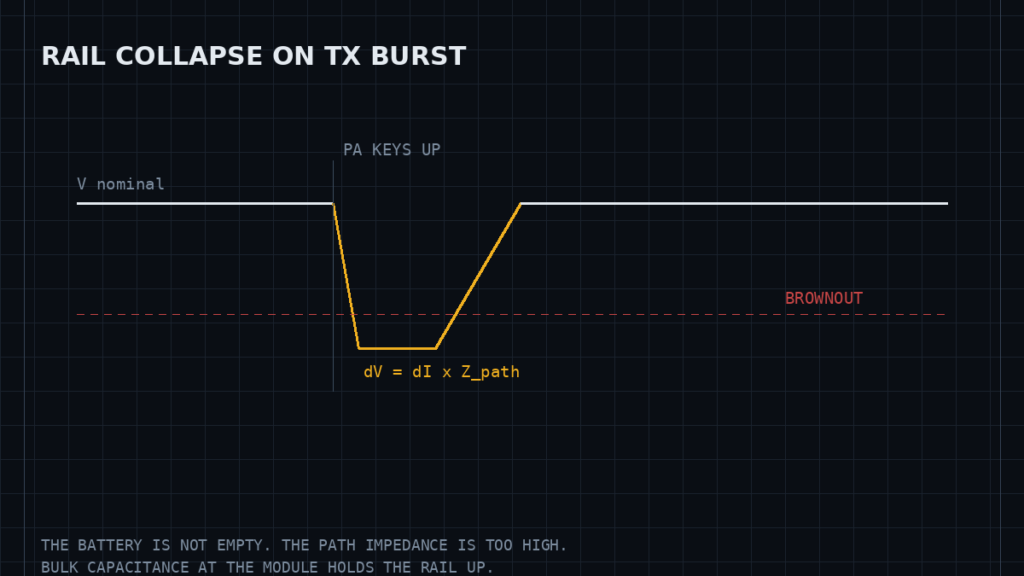
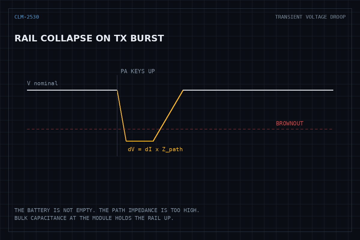
The symptom is distinctive. A sensor runs for weeks, then starts resetting — but only when it has something to report, and more often as the battery ages or the weather turns cold. Battery voltage measured with a multimeter looks fine. Replacing the cell helps for a while, then the fault returns.
This is a transient response failure. The energy in the battery is not the constraint; the impedance between the battery and the chip is.
Why transmitting is the trigger
A radio is the only part of most IoT devices that changes its current draw by two or three orders of magnitude in microseconds. A microcontroller idling at a few milliamps jumps to a few hundred milliamps the instant the power amplifier keys up. Espressif documents this pattern for the ESP32 in its Wi-Fi driver guide and its power management API, both of which treat peak current as a design input rather than an afterthought.
The voltage the chip actually sees is the source voltage minus the drop across everything in between:
Vchip = Vsource − ΔI × Zpath
With a 300 mA step and only half an ohm of total path impedance, that is 150 mV gone in the time it takes the amplifier to turn on. Stack a few contributors together and the rail crosses the brownout threshold.
Where the impedance hides
Cell internal resistance
This is the term that explains the seasonal pattern. A coin cell or an alkaline AA has internal resistance measured in ohms, not milliohms, and that resistance rises as the cell discharges and as temperature falls. A device that is marginal at room temperature on a fresh cell becomes unreliable at 0 °C on a half-used one — while the open-circuit voltage still reads perfectly acceptable, because no current is flowing when you measure it.
Contacts and traces
Spring contacts in a battery holder, a connector, and a long thin power trace each add milliohms. They matter here in a way they never matter for average current.
Regulator loop bandwidth
An LDO or switching converter regulates by feedback, and feedback takes time. A converter with a loop bandwidth in the tens of kilohertz simply cannot respond to a load step that completes in a few microseconds. During that window the regulator is effectively an open circuit and the only thing holding the rail up is local capacitance.
Decoupling is a hierarchy, not a capacitor
The usual mistake is treating decoupling as one part. It is three, each covering a different time scale:
- Bulk capacitance — tens to hundreds of microfarads near the radio module, supplying the burst until the regulator catches up. This is the part that is most often missing or undersized.
- Mid-frequency ceramics — a few microfarads, handling the range between bulk and the fastest edges.
- High-frequency ceramics — sub-microfarad, placed as close to the supply pins as the layout allows, because their effectiveness is dominated by the inductance of the path to the pin rather than by their capacitance.
Note that multilayer ceramic capacitors lose a substantial fraction of their nominal capacitance under DC bias, so a part marked 10 µF may deliver considerably less at the rail voltage. Choosing the dielectric matters as much as choosing the value.
Measuring it properly
A multimeter cannot see this fault. It averages over a window thousands of times longer than the event.
The measurement that resolves it is an oscilloscope on the supply rail, AC-coupled so the droop is not lost in the DC offset, triggered on a falling edge just below the nominal rail. Capture while forcing a transmission. What you are looking for is the depth and duration of the dip, and whether it reaches the brownout threshold in the chip’s datasheet.
Two practical cautions. Probe with a short ground spring directly at the module’s supply pins, not with a long ground lead at the battery terminal — the lead inductance will show you an artefact rather than the rail. And check whether the reset is genuinely a brownout: most microcontrollers expose a reset-reason register, and reading it distinguishes a supply collapse from a watchdog timeout or a firmware fault, which present identically from the outside.
Fixes, in order of effectiveness
- Bulk capacitance at the module supply pins. Directly attacks the dominant term and usually resolves the fault on its own.
- Shorten and widen the power path. Fewer connectors, thicker traces, a solid ground return.
- Reduce peak demand. Lowering transmit power, or preventing a radio transmission and another high-current peripheral from overlapping, cuts the step size directly.
- Change the cell chemistry. Lithium primary cells hold a much lower internal resistance across their discharge curve and across temperature than alkaline cells do.
- Do not simply lower the brownout threshold. It silences the reset without fixing the droop, and undervoltage operation causes data corruption rather than a clean restart.
Why it looks intermittent
Every contributing factor is marginal on its own. Cell resistance, temperature, transmit power, retry behaviour when the link is weak, and where the device happens to be in its discharge curve all move independently. The device fails when several of them line up, which is why the fault appears random and why it becomes steadily more frequent as the battery ages rather than arriving all at once.
Specifications and references
The primary documentation for the interfaces and subsystems discussed above.