Sensor Battery Draining With Nothing Running? Find the Leak
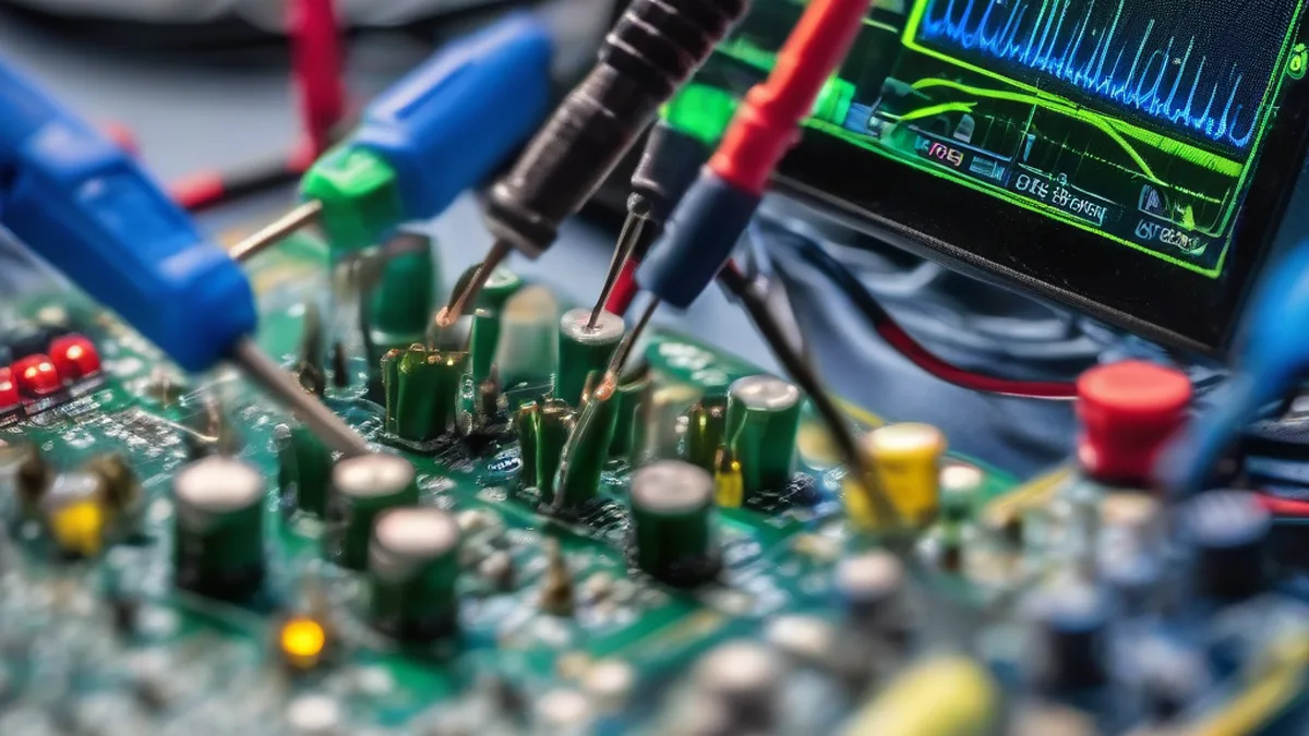
Quick Verdict: Decoding Cryptic Battery Drain
Unexplained rapid battery depletion in smart home sensors often stems from deeply embedded issues: Spurious wake-ups, inefficient deep sleep states, or subtle hardware leakages. Forensic current profiling, logic analysis of wake-up vectors, and meticulous firmware debugging will systematically uncover and rectify these elusive power anomalies. This guide delves into advanced diagnostic techniques, from nanoamp current measurements to interrupt handler optimization, to ensure your battery-powered devices achieve their projected operational lifespans and maintain robust performance.
The Silent Killer: Diagnosing Unexplained Battery Drain in Smart Home Sensors
In the expansive ecosystem of smart home automation, battery-powered sensors are the ubiquitous sentinels, providing critical data points from temperature and humidity to motion and contact states. Their inherent value lies in their wireless freedom and extended operational lifespans, often projected for months or even years. However, a common and deeply frustrating challenge arises when these devices inexplicably deplete their power reserves far sooner than anticipated. This ‘phantom power drain’ isn’t merely an inconvenience; it represents a fundamental failure in the device’s operational integrity, often indicative of complex interplay between firmware inefficiencies, subtle hardware defects, and environmental factors. I approach such anomalies with a forensic mindset, treating each prematurely deceased battery as a crime scene requiring meticulous investigation.
The core of the problem typically revolves around a device’s inability to consistently enter and maintain its lowest power, ‘deep sleep’ states, or its tendency to experience ‘spurious wake-ups.’ These events, often imperceptible without specialized equipment, can dramatically increase the average current consumption, transforming a projected year of operation into mere weeks. Understanding and rectifying these issues requires moving beyond superficial observations and diving into the intricate dance of microcontrollers, power management units, radio transceivers, and sensor interfaces.
Deep Dive: Unmasking the Culprits Behind Premature Battery Failure
The causes of excessive battery drain are multifaceted, often requiring a layered diagnostic approach. We can broadly categorize them into firmware, hardware, and environmental factors.
Firmware-Level Power Inefficiencies
At the heart of every smart sensor lies its embedded firmware, dictating every operational state. Inefficiencies here are a prime suspect:
- Incorrect Sleep State Entry/Exit: Many microcontrollers (MCUs) offer various low-power modes (e.g., deep sleep, light sleep, standby). Failing to correctly configure or enter the lowest power mode, or having a buggy exit routine that leaves peripherals powered on unnecessarily, can be catastrophic for battery life. This often involves ensuring all unused GPIOs are properly configured (e.g., pull-up/down, input/output), internal clocks are gated, and power to non-essential modules (like ADC, SPI, I²C buses) is cut.
- Inefficient Interrupt Service Routines (ISRs): A common wake-up mechanism is an interrupt from a sensor or external event. If the ISR is poorly optimized, spending too long processing or performing unnecessary tasks before returning to sleep, it can significantly impact average current. Furthermore, ‘bouncing’ or noisy sensor inputs can trigger multiple, rapid interrupts, leading to a series of short, high-power wake cycles.
- Unnecessary Polling vs. Event-Driven Architecture: Some firmware designs resort to polling sensors or network status at fixed intervals, even when event-driven interrupts would be more efficient. While simpler to implement, polling keeps the MCU awake and active more often than necessary.
- Radio Transceiver Management: The wireless module (Zigbee, Thread, Wi-Fi, Bluetooth LE) is typically the most power-hungry component. Firmware must minimize radio-on time, ensuring it only transmits or receives when absolutely required, and quickly returns to its own low-power state. Extended beaconing intervals or retransmission attempts due to poor network conditions can also drain power.
- Watchdog Timer Misconfiguration: While crucial for system reliability, an improperly configured watchdog timer could reset the device prematurely, leading to repeated boot cycles, each consuming significant power.
Hardware-Level Leakage and Defects
Even with perfect firmware, hardware issues can silently siphon power:
- Component Leakage Currents: Faulty or low-quality passive components (capacitors, resistors) or active components (MOSFETs, voltage regulators) can exhibit higher-than-specified leakage currents, especially at elevated temperatures.
- Poor PCB Design: Inadequate isolation between power planes, insufficient ground planes, or traces running too close to high-frequency signals can induce parasitic currents or increase noise susceptibility, leading to spurious wake-ups.
- Faulty Power Management ICs (PMICs): A defective PMIC or voltage regulator might fail to enter its own low-power mode or have higher quiescent current than specified.
- Sensor Interface Issues: Some sensors, even in their lowest power states, might draw excessive current if not properly interfaced or if their power rails aren’t correctly managed by the MCU. For instance, leaving pull-up resistors active on an I²C bus when the master MCU is in deep sleep can cause significant leakage.
Environmental and External Factors
Sometimes the problem lies outside the device’s immediate hardware or software:
- RF Interference: Strong electromagnetic interference (EMI) or radio frequency (RF) noise in the environment can sometimes couple into sensor inputs or even MCU pins, triggering false interrupts and waking the device. A critical aspect of RF interference in the 2.4 GHz band, commonly used by Wi-Fi, Zigbee, and Thread, is channel overlap. Wi-Fi channels are 20 MHz wide, while 802.15.4 Zigbee/Thread channels are 5 MHz wide and spaced 5 MHz apart. This leads to significant interference if not managed correctly:
- Wi-Fi Channel 1 (center 2412 MHz, band 2401-2423 MHz) heavily overlaps with Zigbee/Thread channels 11-14.
- Wi-Fi Channel 6 (center 2437 MHz, band 2426-2448 MHz) heavily overlaps with Zigbee/Thread channels 16-19.
- Wi-Fi Channel 11 (center 2462 MHz, band 2451-2473 MHz) heavily overlaps with Zigbee/Thread channels 21-24.
For optimal coexistence and minimal interference, Zigbee/Thread channel 26 (centered at 2480 MHz) is generally recommended as it falls entirely outside the primary Wi-Fi channels 1, 6, and 11 spectrums, offering the clearest path for 802.15.4 devices. Zigbee/Thread channel 25 (centered at 2475 MHz) has a minimal overlap with the very upper edge of Wi-Fi Channel 11, but is still significantly clearer than other overlapping channels. Conversely, choosing Wi-Fi channels 1, 6, or 11 (non-overlapping) and then selecting a Zigbee/Thread channel that avoids these specific Wi-Fi channels is crucial for network stability and, consequently, battery life.
Bluetooth Low Energy (BLE), another common smart home protocol, also operates in the 2.4 GHz ISM band but employs different strategies. Unlike Classic Bluetooth’s 79 channels, BLE utilizes 40 channels, each 2 MHz wide. Crucially, BLE reserves three dedicated advertising channels (channels 37, 38, and 39) that are strategically placed in the spectral gaps between the primary Wi-Fi channels 1, 6, and 11 to minimize interference during device discovery. For data communication, BLE uses Adaptive Frequency Hopping (AFH) to dynamically identify and avoid congested channels, further enhancing its coexistence with Wi-Fi and other 2.4 GHz technologies.
- Sensor Noise: The physical environment itself can cause a sensor to trigger excessively. For instance, a motion sensor facing a window with moving curtains or a temperature sensor placed near a fluctuating heat source might generate frequent, legitimate (but undesirable) events.
- Network Congestion/Stability: If the smart home network (Zigbee, Thread, Wi-Fi) is unstable, the sensor might spend more time and power attempting to re-establish connectivity or retransmit data, leading to higher average current draw.
Forensic Methodology: Pinpointing the Power Drain
A systematic, forensic approach is essential. This involves high-precision current profiling, logic analysis, and targeted firmware debugging.
Step 1: Baseline Current Profiling
The first step is to accurately measure the device’s current consumption across its various operational states. This requires a high-precision current meter (e.g., a source measure unit or a specialized power profiler) capable of resolving nanoampere-level currents and capturing transient spikes.
- Measure Deep Sleep Current: This is the most critical measurement. The device should be in its lowest power state, with no active radio or sensors. Compare this to the MCU and component datasheets’ specified quiescent currents.
- Measure Active Current (Radio Tx/Rx): Trigger a communication event (e.g., send a sensor reading) and measure the peak current during radio transmission and reception.
- Measure Active Current (Sensor Readout): Trigger a sensor reading without radio activity and measure the current.
- Measure Wake-up Transient: Use an oscilloscope with a current probe or a fast-sampling current meter to capture the current spike during the transition from deep sleep to active state. The duration and magnitude of this spike are crucial.
A typical current profile for a well-optimized battery-powered sensor might look like this:
| Operational State | Typical Current (MCU & Radio Module) | Key Considerations |
|---|---|---|
| Deep Sleep / Hibernate | 0.5 µA – 10 µA | Lowest power state; RTC or external interrupt wake-up. All non-essential peripherals powered down. Expect deviations if internal pull-ups or unused GPIOs are misconfigured. |
| Light Sleep / Standby | 100 µA – 1 mA | CPU paused, some peripherals retained. Faster wake-up than deep sleep. Often used for short idle periods or when retaining RAM content is critical. |
| Active (MCU Only) | 5 mA – 50 mA | CPU running, executing code, processing sensor data. Current varies significantly with clock speed and peripheral usage (e.g., ADC conversions, internal flash access). |
| Active (Radio Tx/Rx) | 10 mA – 150 mA (peak) | Highest power consumption state. Duration must be minimized. Network congestion or weak signal strength can prolong this state, leading to higher average current. |
| Wake-up Transient | 50 mA – 200 mA (for <100 ms) | Short burst of high current as MCU and peripherals power up and stabilize. Frequency of these transients significantly impacts average power. |
Step 2: Identifying Wake-Up Sources with Logic Analysis
If the deep sleep current is acceptable but the average current is high, the device is likely waking up too frequently. This is where a logic analyzer becomes indispensable.
┌──────────────────┐     ┌───────────────────┐     ┌───────────────────┐
│   External Event │─────►│   Sensor Module   │─────►│    MCU GPIO       │
│ (e.g., Motion,   │     │ (e.g., PIR, Mag)  │     │   (Interrupt Pin) │
│   Door Open)     │     └───────────────────┘     └───────────────────┘
└──────────────────┘               ▲                             │
                                   │                             │
┌──────────────────┐     ┌───────────────────┐     ┌───────────────────┐
│   RTC Timer      │─────►│   MCU Internal    │     │                   │
│ (Periodic Wake)  │     │   Wake-Up Logic   │     │                   │
└──────────────────┘     └───────────────────┘     │                   │
                                   │             ┌───▼───────────────┐
                                   │             │                   │
                                   └─────────────┤    Microcontroller    │
                                                 │     (MCU)         │
                                                 │                   │
                                                 └───────────┬───────┘
                                                             │
                                                             ▼
                                                 ┌───────────────────┐
                                                 │   Power Management  │
                                                 │   Unit (PMU)      │
                                                 └───────────────────┘
                                                             │
                                                             ▼
                                                 ┌───────────────────┐
                                                 │      Battery      │
                                                 └───────────────────┘

Simplified Power Management and Wake-Up Architecture for a Battery-Powered Smart Sensor
Connect the logic analyzer to potential wake-up sources:
- MCU Interrupt Pins: Monitor GPIOs connected to external sensors (PIR, contact switches, etc.). Look for unexpected toggles.
- RTC Output: If the MCU has an external Real-Time Clock (RTC) or a dedicated RTC wake-up pin, monitor its output.
- Communication Module Wake-up Pin: Some radio modules have a dedicated wake-up pin from the MCU.
- Power Management Unit (PMU) Signals: If present, monitor signals indicating power state transitions.
By correlating current spikes observed on the oscilloscope with logic analyzer traces, you can identify precisely which event is triggering the wake-up. For instance, if a PIR sensor’s output is toggling frequently without actual motion, investigate its sensitivity, placement, or susceptibility to EMI.
Step 3: Targeted Firmware Debugging
Once a spurious wake-up source or high deep-sleep current is identified, firmware debugging is the next step. Use a JTAG/SWD debugger:
- Verify Sleep State Entry: Set breakpoints just before the MCU enters a low-power mode and immediately after it wakes up. Inspect register values to confirm that all non-essential peripherals are indeed powered down and clocks are gated.
- Analyze ISR Execution: If an interrupt is causing frequent wake-ups, step through the ISR code. Look for delays, unnecessary computations, or calls to functions that require active peripherals. Implement debouncing routines for noisy inputs.
- Optimize Radio Stack: Examine the radio communication stack’s behavior. Are retransmissions excessive? Is the radio staying awake longer than needed? Are beaconing intervals appropriate for the application?
Step-by-Step Troubleshooting Guide for Power Anomalies
This systematic approach helps isolate and resolve the root cause of phantom power drain.
| Step # | Action / Diagnostic | Expected Result / Anomaly Indication | Root Cause / Remediation |
|---|---|---|---|
| 1 | Measure Deep Sleep Current (using high-precision multimeter/power profiler) | Expected: <10 µA. Anomaly: >100 µA. | High Deep Sleep Current: Likely hardware leakage (faulty components, poor PCB design) or firmware failing to power down peripherals/gate clocks. Use JTAG to verify register states. |
| 2 | Monitor Wake-Up Pins with Logic Analyzer (e.g., sensor interrupt, RTC) | Expected: Infrequent, deliberate toggles. Anomaly: Frequent, unexpected toggles or ‘chatter’. | Spurious Wake-ups: Investigate sensor input noise (EMI, environmental factors), firmware debouncing issues, or external RF interference. |
| 3 | Profile Radio Activity (using current probe on oscilloscope, or network sniffer) | Expected: Short, infrequent Tx/Rx bursts. Anomaly: Extended radio-on time, frequent retransmissions. | Excessive Radio Use: Poor network signal strength, network congestion, or inefficient radio stack implementation. Optimize network topology, reduce data payload size, or review radio firmware. |
| 4 | Step-Through ISRs with Debugger (JTAG/SWD) | Expected: Quick, minimal execution path. Anomaly: Long execution times, unnecessary function calls. | Inefficient ISRs: Refactor ISRs to be as lean as possible. Defer complex processing to the main loop after waking up. Implement proper input debouncing. |
| 5 | Environmental Scan (using spectrum analyzer, EMI probe) | Expected: Clean RF environment, minimal conducted noise. Anomaly: High levels of broadband RF noise, power line transients. | External Interference: Relocate sensor, shield sensitive inputs, add filtering (capacitors, ferrite beads) to power lines or signal paths. |
Advanced Mitigation Strategies
- Ultra-Low Power (ULP) Coprocessors: For MCUs that support them (e.g., ESP32), offload simple tasks like sensor monitoring to a ULP coprocessor while the main CPU is in deep sleep. This allows for very low power sensing without fully waking the main CPU.
- Power Gating: Implement hardware-level power gating for specific peripherals or even the radio module itself using load switches. Ensure these are properly controlled by the MCU to completely cut power when not in use.
- Dynamic Frequency Scaling (DFS): Adjust the MCU’s clock frequency dynamically based on processing load. Lowering the clock speed when only minimal processing is required can significantly reduce active current.
- Optimized Battery Chemistry Management: For rechargeable batteries, implement sophisticated battery management systems (BMS) that accurately monitor state of charge, balance cells, and optimize charging cycles to prolong overall battery health.
- Network Parameter Tuning: For mesh networks like Zigbee or Thread, experiment with network parameters such as polling intervals, retransmission counts, and beaconing rates to find the optimal balance between responsiveness and power consumption for your specific deployment.
Frequently Asked Questions About Smart Home Sensor Battery Life
What is ‘deep sleep’ and why is it crucial for battery-powered smart sensors?
Deep sleep is the lowest power consumption state for a microcontroller, where most internal peripherals, the CPU, and often a significant portion of RAM are powered down. Only essential components, like a Real-Time Clock (RTC) or specific wake-up pins, remain active. It’s crucial because it allows the sensor to spend the vast majority of its operational time drawing only microamperes or even nanoamperes of current, dramatically extending battery life by minimizing the average power draw between active events.
How can environmental factors affect battery life, beyond direct temperature impact?
Beyond direct temperature effects on battery chemistry, environmental factors like electromagnetic interference (EMI) or radio frequency (RF) noise can cause spurious wake-ups. For instance, a high-power switching LED driver or a poorly shielded appliance might emit broadband noise that is picked up by a sensor’s input lines, triggering false interrupts and waking the device from its low-power state. Similarly, a motion sensor placed near a heating vent or window with moving curtains could experience legitimate but undesired triggers, leading to more frequent active cycles.
What’s the difference between average current and peak current, and why are both important for battery life?
Peak current is the maximum current drawn during a specific operation, such as radio transmission or sensor activation. It’s critical for ensuring the battery and power supply can deliver enough instantaneous power without voltage sag. Average current is the total charge consumed over a period, divided by that period. It’s the primary determinant of overall battery life. A device might have high peak currents for short durations but still achieve long battery life if its average current (dominated by deep sleep current and frequency of wake-ups) is low. Both are important: Peak current ensures reliability, while average current dictates longevity.
Can a weak Wi-Fi or Zigbee signal impact my smart sensor’s battery life?
Absolutely. A weak wireless signal leads to increased retransmission attempts, longer radio-on times, and higher power consumption as the device struggles to communicate reliably with the hub or access point. If the signal is consistently poor, the device may spend significantly more time and energy just trying to send a single sensor reading or acknowledge a command, dramatically reducing battery life. Optimizing network coverage and signal strength is a key factor in maximizing battery endurance for connected sensors.
What diagnostic tools are essential for forensic battery drain analysis?
For a thorough forensic analysis, essential tools include:
- High-Precision Current Meter/Power Profiler: Capable of measuring nanoampere to ampere currents with high resolution and fast sampling rates to capture transient events.
- Digital Oscilloscope: To visualize current spikes (with a current probe) and voltage rail stability during state transitions.
- Logic Analyzer: To monitor digital signals and identify precise wake-up sources by correlating interrupt lines with current profiles.
- JTAG/SWD Debugger: For real-time firmware debugging, stepping through code, and inspecting register states to verify sleep mode entry/exit and ISR execution.
- RF Spectrum Analyzer (optional but useful): To identify potential external RF interference causing spurious wake-ups.
Conclusion
The quest for extended battery life in smart home sensors is a pursuit of precision engineering, demanding a holistic understanding of hardware, firmware, and environmental interactions. Phantom power drain is rarely a simple issue; it’s a diagnostic puzzle that requires the rigor of forensic analysis. By systematically profiling current consumption, meticulously analyzing wake-up vectors, and diligently optimizing firmware, you can transform underperforming devices into reliable, long-lasting components of a robust smart home ecosystem. The investment in these advanced diagnostic techniques not only saves on battery replacement costs but fundamentally enhances the reliability and user experience of the entire smart home infrastructure.
About these guides
These guides are compiled and maintained by the Smart Home Expert editorial desk. Each one is built from manufacturer documentation and the published Zigbee, Z-Wave, Thread and Wi-Fi specifications, then written up as a diagnostic sequence you can follow in order. Found something that does not match your hardware? Tell us and we will correct the sheet.
Specifications and references
The primary documentation for the protocols and products discussed above. Where this guide gives a figure — a frequency, a voltage, a timeout — these are where it comes from.