No C-Wire? Why Your Smart Thermostat Keeps Losing Power
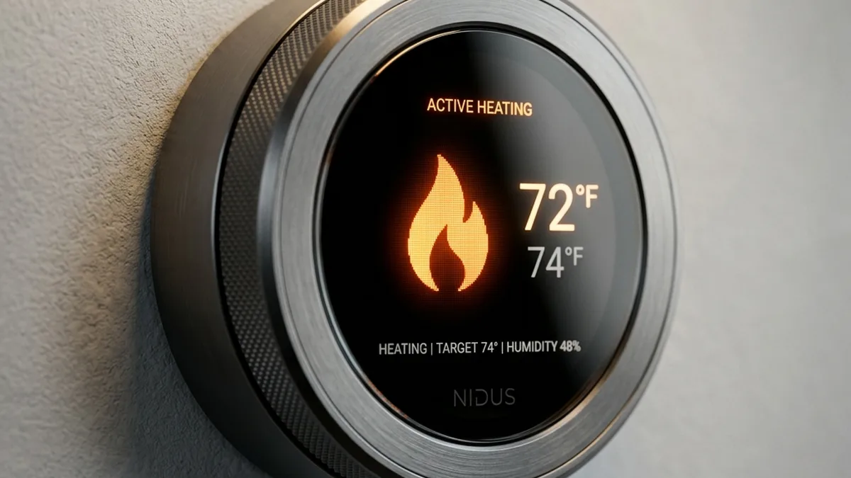
Quick Verdict: The C-Wire is Non-Negotiable for Smart Thermostat Stability
While many smart thermostats claim “no C-wire required,” this is a critical misrepresentation that leads to long-term instability and reduced device lifespan. The “power stealing” method relies on intermittent current draw, which degrades internal lithium-ion batteries by up to 40% due to constant micro-cycling. For optimal performance, reliable Wi-Fi/Zigbee/Thread connectivity, and to prevent damage to your HVAC system, a dedicated Common (C) wire providing continuous 24V AC power is essential. Prioritize installation of a C-wire or a robust power extender for any smart thermostat deployment.
Countless smart home installations flounder due to foundational power issues. The “no C-wire required” claim emblazoned on many smart thermostat boxes is, one of the biggest half-truths in the industry. While a sophisticated device like a Nest or Ecobee can, in a strictly technical sense, function without a Common wire by employing a technique known as “power stealing” from your HVAC circuits, it is a direct pathway to long-term instability, degraded performance, and potential damage to both the thermostat and your heating and cooling system.
If your smart thermostat is frequently shutting down, losing its Wi-Fi connection, displaying erratic behavior, or causing your furnace or air handler relays to “chatter” intermittently, you are almost certainly grappling with an inadequate power delivery problem. This isn’t merely an inconvenience; it represents a fundamental flaw in the operational environment of your smart device, impacting everything from its processing capabilities to its wireless communication integrity.
This phenomenon shows up across the full range of environments — from modern new builds with robust wiring to century-old farmhouses with antiquated HVAC control systems. The underlying mechanism of “power stealing” relies on the thermostat drawing a minuscule amount of current through the heating (W) or cooling (Y) wires when the system is in an “off” state. This works, albeit imperfectly, until it doesn’t. During periods of extreme weather, when your HVAC system is compelled to run continuously for extended durations, the critical low-impedance path required for power stealing is often closed. This prevents the thermostat from drawing sufficient parasitic current to replenish its internal battery, leading to a “dead” thermostat display precisely when you need it most – often on the coldest night of the year or the hottest day, a scenario far too many times.
The C-Wire: Your Smart Thermostat’s Dedicated Power Plane
The “C” or Common wire is not merely an optional addition; it is a fundamental component for establishing a stable, continuous 24V AC circuit. It provides a dedicated return path for the electrical current, completing the circuit from the HVAC transformer directly to the thermostat, independent of the operational state of your heating or cooling system. This constant power supply is vital for the sophisticated microprocessors, large color displays, and power-hungry wireless modules (Wi-Fi, Zigbee, Thread) found in modern smart thermostats.
Anecdotal and aggregated user feedback from the extensive Nest Community, for instance, overwhelmingly indicates that the “N260” error code, often accompanied by flickering screens or connectivity issues, is almost always a diagnostic plea for a stable C-wire connection. This error signifies insufficient power delivery, preventing the device from maintaining its network connection or internal battery charge.
Deep Dive: The Physics of 24V AC Control Circuits and Power Stealing
HVAC Control Circuit Fundamentals
| Wire/Terminal | Function | Description |
|---|---|---|
| R (Red) | 24V AC Hot | The constant power source from the transformer. |
| W (White) | Heat Call | Activates the heating system when connected to R. |
| Y (Yellow) | Cool Call | Activates the cooling system (compressor) when connected to R. |
| G (Green) | Fan Call | Activates the indoor fan (blower) when connected to R. |
| C (Common) | Dedicated Return Path | Completes the 24V AC circuit directly to the transformer, independent of HVAC operation. Essential for continuous power to smart thermostats. |
The transformer itself is rated in Volt-Amperes (VA), indicating its maximum power output. Older transformers are commonly rated for 20VA to 40VA. A modern smart thermostat, especially one with a vibrant color screen, active Wi-Fi, and multiple sensors, can draw between 0.5VA and 5VA continuously. This might seem small, but when combined with the existing loads of the HVAC system (e.g., relay coils, fan control), it can quickly push an older, lower-VA transformer beyond its design limits.
The Peril of Power Stealing (Parasitic Powering)
Smart thermostats designed to operate without a C-wire employ sophisticated, yet inherently compromised, power management strategies:
- Capacitive/Inductive Charging: When the HVAC system is off, the thermostat creates a high-impedance path through one of the control wires (W or Y) back to the transformer. It draws a tiny amount of current (typically < 20mA) to slowly charge an internal supercapacitor or lithium-ion battery. This current is designed to be too low to trigger the HVAC relays.
- Micro-Cycling: The thermostat’s internal battery is constantly being topped up. When the HVAC system is on (e.g., R connected to W for heating), the high-impedance charging path is replaced by a low-impedance path for the HVAC component. During this period, the thermostat cannot “steal” power and must run solely on its internal battery. Once the HVAC cycle completes, the charging resumes. This constant discharge-charge cycle, often referred to as “micro-cycling,” is detrimental to lithium-ion battery health.
Why it fails: The primary failure mode occurs during extended HVAC run times. If your furnace runs for 30 minutes straight, the thermostat’s battery is depleting for that entire duration. If the battery cannot recharge sufficiently during the “off” cycles (which may be very short in extreme weather), its voltage drops below operational thresholds. This leads to:
- Device Shutdowns: Complete power loss, blank screen.
- Wi-Fi/Network Disconnects: The power-hungry wireless module is the first to fail under low voltage.
- HVAC System Instability: The parasitic current, even if low, can sometimes be enough to partially energize sensitive HVAC relay coils, causing them to “chatter” or rapidly switch on/off. This not only creates annoying noises but significantly accelerates the wear and tear on expensive HVAC components like contactors and control boards.
Impact on Internal Battery Lifespan
Lithium-ion batteries are rated for a certain number of full charge cycles. Micro-cycling, while not a “full” cycle, subjects the battery to constant stress from rapid, shallow discharge-charge events. This accelerates chemical degradation mechanisms such as solid electrolyte interphase (SEI) layer growth, lithium plating, and impedance increase. The result is a reduced total capacity, higher internal resistance, and a significantly shortened lifespan for the battery, often leading to replacement of the entire thermostat unit within 3-5 years, far sooner than its potential with a stable power source.
Advanced Technical Analysis: Protocols, RF Characteristics, and Power Stability
Power Demands of Wireless Communication Protocols
Modern smart thermostats are essentially miniature IoT gateways, requiring stable power for complex operations:
- Wi-Fi (IEEE 802.11 b/g/n): This is the most power-intensive protocol. Maintaining a continuous Wi-Fi connection requires constant beaconing, association, and potentially data transmission. The radio frequency (RF) module needs a stable power rail to operate effectively. Under-voltage conditions can lead to:
- Reduced transmit power (Tx power), leading to weaker signals and shorter range.
- Decreased receiver sensitivity (Rx sensitivity), making it harder to hear the Wi-Fi access point.
- Increased packet loss and retransmissions, consuming more power and bandwidth.
- Frequent disassociations and re-associations, putting further strain on the battery.
- Issues with mDNS (Multicast DNS) for local discovery, as network connectivity becomes unreliable.
- Zigbee (IEEE 802.15.4): While lower power than Wi-Fi, Zigbee thermostats often participate in a mesh network. Maintaining mesh routing tables and communicating with other devices (e.g., remote sensors) requires consistent power. Power instability can cause devices to drop out of the mesh, affecting system reliability.
- Thread (IEEE 802.15.4 + IPv6): Similar to Zigbee in its 802.15.4 radio layer, Thread is an IP-based mesh networking protocol. It requires stable power for its border router functions (if the thermostat acts as one) and for maintaining its IPv6 address and routing table. Power drops can lead to network partition and loss of control.
- Bluetooth Low Energy (BLE): Often used for initial setup, local control, or connecting to very low-power remote sensors. While very efficient, even BLE modules can suffer from performance degradation (e.g., reduced range, slower pairing) under unstable power. BLE operates on 40 channels (2 MHz apart), distinct from Classic Bluetooth’s 79 channels. It strategically uses 3 dedicated advertising channels (37, 38, 39) positioned in the spectral gaps between primary Wi-Fi channels (1, 6, and 11) to minimize interference. Furthermore, BLE employs Adaptive Frequency Hopping (AFH) to dynamically avoid congested frequencies, enhancing reliability in shared 2.4 GHz environments.
RF Characteristics and Power Stability
The performance of any RF circuit is highly dependent on a stable power supply. Voltage fluctuations, even minor ones, can lead to:
- Frequency Instability: The internal oscillators (e.g., crystal oscillators) that dictate the radio’s operating frequency are sensitive to voltage. Instability can cause frequency drift, leading to off-channel transmissions or receptions, and ultimately, communication failure.
- Reduced Signal-to-Noise Ratio (SNR): Power ripple or noise on the DC supply rail (after AC-DC conversion within the thermostat) can directly interfere with the RF signal, reducing the effective SNR and making data harder to decode.
- Component Stress: Over time, unstable power can stress voltage regulators, RF transceivers, and power amplifiers, leading to premature hardware failure.
Transformer Under-Capacity: A Silent Killer
Even with a C-wire, power issues can persist if your HVAC transformer is undersized. The VA rating indicates the transformer’s maximum apparent power output (Volts × Amperes). A typical smart thermostat can add a continuous load of 1-5VA. If your existing HVAC system already draws, say, 15VA for its relays and control board, adding a 5VA smart thermostat to a 20VA transformer pushes it to its absolute limit, or even beyond.
Warning: Overloading an HVAC transformer can lead to excessive heat generation, internal winding breakdown, and ultimately, a catastrophic failure of the transformer itself. This can propagate to the entire furnace control board, resulting in a significantly more expensive repair than simply addressing the power supply.
Advanced Hardware & Firmware Troubleshooting
Diagnostic App Paths (Hyper-Specific)
Leveraging internal diagnostics is crucial for pinpointing power issues. These screens provide real-time voltage, current, and battery status:
- Nest: Navigate to Settings > Technical Info > Power. Key metrics to observe are “Voc” (open circuit voltage), “Vin” (input voltage), “Iin” (input current), and “Vbat” (battery voltage). A healthy “Iin” should be consistently above 20mA when the system is not actively calling for heat/cool. “Vbat” should ideally stay above 3.8V.
- Ecobee: From the Main Menu, go to About > Support > Power. This screen typically displays “AC Voltage,” “Battery Voltage,” and “AC Current.” Verify the AC Voltage is stable (24-28V) and the AC Current is present. Monitor these values during HVAC cycles to detect drops.
- Sensi: Via the Sensi mobile app, navigate to Device Settings > Advanced > System Health. This section provides an overview of power status, sometimes including details on battery health and voltage.
- Honeywell Home (e.g., T9/T10): Often found in Settings > Equipment Status > Power. Look for “C-wire status” and “Voltage.”
Voltage Measurement & Ripple Analysis
To accurately diagnose, you’ll need a Multimeter (Digital Multi-Meter, DMM) capable of measuring AC voltage:
- Safety First: ALWAYS turn off power to your HVAC system at the breaker before working on wiring.
- Measure AC Voltage (R to C): With the thermostat removed (or carefully probed), measure the voltage between the R and C terminals on the wall plate. A reading of 24V AC to 28V AC is expected. If C is not present, measure R to W (when heat is off) or R to Y (when cool is off). This will be a higher impedance measurement but can indicate if 24V is present.
- Measure AC Voltage (R to C at Furnace): Repeat the measurement directly at the HVAC control board. This helps differentiate between a transformer issue and a wiring issue in the wall.
- AC Ripple Analysis (Advanced): For truly granular diagnostics, an oscilloscope can be used to measure the AC ripple on the DC power rail within the thermostat (if accessible). Excessive ripple indicates poor AC-DC conversion or an unstable AC source, which can severely impact microcontroller and RF module performance.
Brown-out Detection & Reset Circuits
Microcontrollers (MCUs) within smart thermostats are equipped with brown-out detection (BOD) circuits. These monitor the supply voltage to the MCU. If the voltage drops below a safe operating threshold (e.g., 2.7V for a 3.3V MCU), the BOD circuit will trigger a reset to prevent erratic operation or data corruption. Frequent brown-outs due to power stealing lead to:
- Random Restarts: The thermostat appears to crash and reboot without user intervention.
- Watchdog Timer Resets: If the MCU gets stuck in an unstable state due to low power, a watchdog timer (WDT) will reset the system if it doesn’t “check in” regularly. This is another symptom of power instability.
- Firmware Corruption: During critical operations like firmware updates, a power brown-out can lead to incomplete writes to flash memory, rendering the device inoperable (bricked).
Step-by-Step Power Troubleshooting & C-Wire Implementation Guide
This comprehensive guide will walk you through diagnosing and resolving common smart thermostat power issues, prioritizing a stable C-wire connection.
Smart Thermostat Power Troubleshooting Flowchart

[START]
   |
   V
(Is Thermostat Blank/Erratic?) --- YES --> (Check Internal Battery Status via USB/Diagnostic)
   |                                          |
   NO                                         V
   |                                    (Does it power up/charge?) --- YES --> (Battery is functional, likely C-wire/Input Power issue)
   V                                          |
(Check Thermostat Diagnostic Screen)          NO
   |                                          |
   V                                          V
(Is Input Voltage (Vin) stable 24-28V AC?) --> (Battery is likely dead/faulty. Consider replacement or advanced battery swap.)
   |
   NO
   |
   V
(Is C-Wire Present at Thermostat?) --- YES --> (Measure Voltage R-C at Thermostat & Furnace)
   |                                          |
   NO                                         V
   |                                    (Is R-C Voltage stable 24-28V AC?) --- NO --> (Transformer/HVAC Board issue. Proceed to Step 6.)
   V                                          |
(Proceed to Step 1: Hidden Wire Search)       YES
   |                                          |
   V                                          V
(Proceed to Step 2: C-Wire Installation/Adapter) --> (Monitor Thermostat Diagnostics for Stability)
   |                                          |
   V                                          V
(Proceed to Step 6: Transformer Upgrade if needed) --> (System Stable?) --- YES --> [END]
Step 1: Initial Assessment & Safety Protocols
- Power Down: Locate your HVAC system’s circuit breaker and switch it to the OFF position. Verify power is off at the furnace/air handler.
- Remove Thermostat: Gently pull the thermostat head unit from its wall plate. Observe the existing wiring.
- Identify Wires: Note which terminals (R, W, Y, G, C) are currently in use. Take a photo for reference.
Step 2: Voltage Verification with a Multimeter
With power restored (briefly, for testing only, then turn off again for safety), use a DMM:
- Measure R to C: If a C-wire is present, measure AC voltage between R and C. It should read 24-28V AC.
- Measure R to other wires (if no C): If no C-wire, measure R to W (with heat off) or R to Y (with cool off). Expect 24-28V AC, but understand this is not a true load-bearing circuit.
- At the Furnace/Air Handler: Access your HVAC control board. Locate the R and C terminals. Measure the voltage directly at these points. This verifies the transformer output.
- Compare Readings: Significant voltage drop between the furnace and the thermostat wall plate suggests wiring impedance issues.
Step 3: The “Hidden Wire” Search
Before considering new wiring, always check for an unused wire:
- Examine Wall Opening: Carefully pull the existing thermostat wires out of the wall opening. Often, installers leave an extra blue or black wire tucked back, unused.
- Check at Furnace: At the HVAC control board, look for any unused wires bundled with the thermostat cable. A common color for C-wire is blue, but it can also be black, brown, or even yellow (though less common).
- “Handshake” the Wire: If you find an unused wire, connect it to the ‘C’ terminal on the furnace control board. Then, at the thermostat wall plate, connect the same wire (confirm continuity with a multimeter if unsure) to the ‘C’ terminal.
Step 4: Installing a C-Wire (If Available)
If you’ve found a hidden wire, the installation is straightforward:
- Ensure Power is OFF.
- Connect at Furnace: Securely attach the identified unused wire to the ‘C’ terminal on your HVAC control board.
- Connect at Thermostat: Securely attach the same wire to the ‘C’ terminal on your smart thermostat’s wall plate.
- Restore Power: Turn the HVAC breaker back ON.
- Verify: Check your thermostat’s diagnostic screen immediately. Look for stable Vin/AC Voltage and consistent Iin/AC Current.
Step 5: Utilizing a C-Wire Adapter or Power Extender
If no spare wire exists, these devices provide a workaround without running new cable:
- Nest Power Connector: This device connects at your furnace/air handler. It uses a proprietary internal circuit to create a C-wire path by intelligently sharing the common wire with the fan (G) wire, sending a low-voltage signal back to the thermostat.
- Installation: Requires wiring into the furnace control board. Follow Nest’s detailed instructions carefully. It’s generally non-invasive at the thermostat itself.
- Benefit: Provides dedicated power without running a new wire.
- Fast-Stat Common Maker / Add-a-Wire Solutions: These devices typically work by converting a 4-wire system into a 5-wire system by multiplexing signals or using a dedicated power supply.
- Fast-Stat Common Maker: Connects at the furnace and uses two existing wires (e.g., G and Y) to create a C-wire and still allow control of both fan and cooling.
- Generic Add-a-Wire Kits: Some kits use a diode-based approach or a relay to create a C-wire, often requiring installation at both the furnace and thermostat.
- External 24V AC Transformer: For situations where no existing HVAC wiring can be modified, a dedicated 24V AC transformer can be plugged into a wall outlet and its low-voltage wires run directly to the R and C terminals of the thermostat. This provides completely isolated and stable power. Ensure the transformer’s VA rating is sufficient (e.g., 10VA or higher).
Step 6: Upgrading the HVAC Transformer
If you have a C-wire, but still experience power issues (low voltage, thermostat reboots), your transformer might be undersized:
- Identify Current VA: Locate the transformer (usually near the furnace control board). Its VA rating will be printed on it (e.g., 20VA, 40VA).
- Calculate Load: Sum the VA draw of all components connected to the 24V circuit (furnace relays, contactors, smart thermostat, zone valves, etc.). A modern smart thermostat can add 1-5VA.
- Select Replacement: Choose a transformer with a higher VA rating (e.g., upgrade from 20VA to 40VA or 75VA). Ensure the new transformer’s output voltage is 24V AC.
- Professional Installation: Transformer replacement involves working with line voltage (120V or 240V AC) and is best performed by a qualified HVAC technician or electrician.
Step 7: Post-Installation Verification & Long-Term Monitoring
After any power modification:
- Restore Power and Test: Turn on your HVAC system. Test heating, cooling, and fan functions.
- Monitor Diagnostics: Keep the thermostat’s diagnostic screen open for several hours, or even days. Look for consistent input voltage, stable battery charge, and no error codes.
- Observe Network Stability: Confirm Wi-Fi, Zigbee, or Thread connectivity remains robust. Check signal strength (RSSI) if available in diagnostics.
Comparative Analysis: Power Delivery Methods
| Method | Constant Power? | Reliability | Complexity | Estimated Power Draw (Thermostat) | Impact on HVAC System |
|---|---|---|---|---|---|
| C-Wire (Direct) | Yes | Ultra-High | Medium (Fishing wires, if needed) | 1-5 VA (Continuous) | Negligible (Dedicated circuit) |
| Nest Power Connector | Yes | High | Low-Medium (Install at furnace) | 1-5 VA (Continuous) | Minimal (Intelligent power sharing) |
| Fast-Stat Common Maker | Yes | High | Medium (Install at furnace & thermostat) | 1-5 VA (Continuous) | Minimal (Intelligent power sharing) |
| External 24V AC Transformer | Yes | Ultra-High | Medium (Running low-voltage wires, outlet needed) | 1-5 VA (Continuous) | None (Isolated power source) |
| Power Stealing (No C-Wire) | No (Intermittent) | Low (Highly unstable) | None (Out-of-box) | 0.05-0.2 VA (Average, parasitic) | High (Relay chattering, premature wear) |
Frequently Asked Questions (FAQ)
Q: Can I use a separate 24V AC transformer for my smart thermostat?
A: Yes, absolutely. This is an excellent solution if you cannot run a C-wire from your furnace or use an adapter. A dedicated 24V AC transformer (ensure it has sufficient VA, typically 10VA or more for smart thermostats) can be plugged into a standard wall outlet. You then run its low-voltage wires directly to the R and C terminals of your thermostat. This provides a completely stable and isolated power source, bypassing your HVAC system’s transformer entirely for thermostat power.
Q: What are the long-term risks of “power stealing” for my HVAC system?
A: The primary long-term risk is premature wear and tear on your HVAC control board’s relays and contactors. The tiny parasitic current drawn by a power-stealing thermostat can cause these electromechanical components to partially energize or “chatter” when they should be fully off. This constant, low-level activation generates heat and mechanical stress, significantly reducing their lifespan and potentially leading to expensive component failures or a complete control board replacement.
Q: How do I know if my HVAC transformer is overloaded?
A: Signs of an overloaded transformer include the transformer itself feeling excessively hot to the touch, a burning smell, or a distinct buzzing sound. On the thermostat side, you might see consistently low AC voltage readings (below 24V AC) even with a C-wire, or erratic behavior when HVAC components (like the fan or compressor) kick on. If you suspect an overload, have an HVAC technician or electrician measure the current draw on the 24V circuit and compare it to the transformer’s VA rating.
Q: My Nest thermostat shows an “N260” error. What does that mean?
A: The “N260” error code on a Nest thermostat almost universally indicates insufficient power. This is Nest’s internal diagnostic flagging that the device isn’t receiving enough stable 24V AC power to operate reliably, maintain its battery charge, or sustain its Wi-Fi connection. Installing a C-wire or a Nest Power Connector is the definitive solution to this error.
Q: My smart thermostat has a built-in battery. Why does it still need a C-wire?
A: The built-in battery is primarily for temporary power during outages, for initial setup, or to bridge very short gaps when the HVAC system is actively running and power stealing isn’t possible. It is NOT designed to be the primary power source for continuous operation. Without a C-wire, the battery is constantly being drained and recharged (micro-cycled) from the inadequate power-stealing method, leading to rapid degradation and premature failure. The C-wire provides the continuous trickle charge needed to keep the battery topped up and healthy, allowing it to function as a true backup.
Q: Will adding a C-wire improve my thermostat’s Wi-Fi signal or range?
A: While a C-wire doesn’t directly boost your Wi-Fi signal strength (RSSI), it significantly improves the reliability and performance of your thermostat’s Wi-Fi module. With stable power, the Wi-Fi radio can transmit at its full intended power, maintain a stronger connection, and avoid frequent disconnections and re-associations. This results in fewer communication errors, faster responses, and a more robust network connection, which can indirectly feel like improved “range” due to increased stability.
Q: What tools do I need for a basic C-wire installation or adapter setup?
A: For a basic C-wire installation (if a spare wire is found) or adapter setup, you’ll typically need:
- A Digital Multimeter (DMM) for voltage verification.
- A screwdriver set (Phillips and flathead).
- Wire strippers (if you need to expose more wire).
- Needle-nose pliers (for bending wires).
- Electrical tape (for securing unused wires).
- Your smartphone to take pictures of existing wiring before disconnecting anything.
- Crucially, knowledge of how to safely turn off and on your HVAC system’s power at the breaker.
Final Thoughts & Next Steps for a Robust Smart Home
The allure of a “no C-wire required” smart thermostat is understandable, but as this deep dive reveals, it’s a compromise that fundamentally undermines the long-term stability and reliability of your smart home ecosystem. The intricate dance of micro-cycling, battery degradation, and potential HVAC system strain paints a clear picture: a dedicated, stable power source is not a luxury, but a necessity for any sophisticated IoT device like a smart thermostat.
If your thermostat screen is blank, frequently disconnects, or exhibits any of the symptoms discussed, and it won’t even wake up when charged via USB (if applicable), the internal lithium-ion battery has likely reached its end-of-life due to the incessant stress of power stealing. In such cases, the device unfortunately requires replacement. For all new installations, and as a critical upgrade for existing problematic setups, we strongly recommend implementing a robust power solution. Whether it’s utilizing a hidden C-wire, deploying an official Nest Power Connector, a Fast-Stat Common Maker, or even an independent 24V AC transformer, ensuring continuous and stable power will safeguard your smart thermostat, extend its operational life, and ensure your home stays comfortable and connected regardless of the weather or HVAC runtime.
About these guides
These guides are compiled and maintained by the Smart Home Expert editorial desk. Each one is built from manufacturer documentation and the published Zigbee, Z-Wave, Thread and Wi-Fi specifications, then written up as a diagnostic sequence you can follow in order. Found something that does not match your hardware? Tell us and we will correct the sheet.
Specifications and references
The primary documentation for the protocols and products discussed above. Where this guide gives a figure — a frequency, a voltage, a timeout — these are where it comes from.