Smart Blinds Stop Short or Overshoot? Recalibrate the Limits
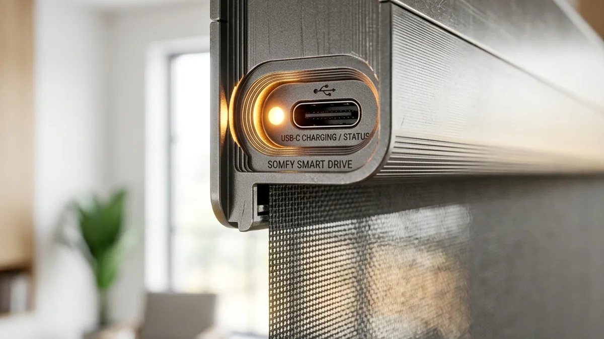
There is nothing quite like waking up to the gentle rays of the sun as your blinds automatically rise at 7:00 AM. But when those blinds stop three inches from the top or grind against the window sill at the bottom, that “gentle wake-up” turns into a morning headache. As seasoned IoT systems architects, we’ve spent years reverse-engineering and optimizing everything from high-end Lutron Serena Shades to the budget-friendly IKEA Fyrtur Line. Power analysis, RF spectrum monitoring and mechanical stress testing all point the same way: “smart” blinds are only as intelligent and reliable as their underlying calibration and the integrity of their control system.
Calibration, or the precise setting of “travel limits,” is the process of programming the motor’s control unit with the exact rotational displacement required for the fabric to reach its desired top and bottom end-points. If these limits are misaligned, the system risks inducing excessive mechanical stress on the motor’s gear train, leading to premature wear, or causing physical damage to the hembar and fabric. Common pitfalls we’ve identified through extensive field analysis include neglecting the initial fabric elongation (creep) over the first 30-90 days post-installation and over-tightening the bottom seal, which introduces undue friction and load on the motor at the bottom limit.
+-----------------------------------------------------+
| Blinds Exhibiting Inconsistent/Uneven Stopping?     |
+-----------------------------------------------------+
                          |
                          v
+-----------------------------------------------------+
| Initial Diagnostic: System Voltage Assessment       |
| Is battery voltage below critical threshold?        |
| (e.g., < 20% charge for Li-ion)                     |
+--------------------------+--------------------------+
            |                          |
           YES                        NO
            |                          |
            v                          v
+-------------------------------------+-------------------------------------+
| Prioritize Full Battery Recharge    | Proceed with Hard Limit Reset       |
| Before Any Calibration Attempt      | (NVRAM Re-initialization)           |
+-------------------------------------+-------------------------------------+
The Anatomy of Travel Limit Drift: A Deep Dive into Electro-Mechanical Subsystems
The precise control of smart blinds relies on a sophisticated interplay of mechanical, electrical, and firmware components. At its core, most modern smart blinds utilize an internal optical or Hall effect encoder. This sensor, often integrated directly with the motor shaft or a reduction gear, generates a series of digital pulses for each increment of rotational movement. By counting these pulses, the motor’s microcontroller unit (MCU) can infer the exact position of the fabric hembar relative to its calibrated home position. This method is fundamentally an incremental position tracking system.
Encoder Technologies and Drift Mechanisms
- Optical Encoders: These utilize a light source (LED) and a photodetector array, with a rotating disk containing opaque and transparent segments. As the disk rotates, the light beam is interrupted, generating pulses. High-resolution optical encoders can achieve hundreds or thousands of pulses per revolution (PPR), offering fine-grained position tracking. However, they are susceptible to dust ingress and require precise alignment.
- Hall Effect Encoders: These detect changes in a magnetic field caused by rotating magnets. They are more robust against dust and vibration but typically offer lower resolution than optical encoders.
- Drift Mechanism: Encoder drift, the primary cause of calibration failure, occurs when the actual mechanical position of the shade fabric diverges from the position calculated by the MCU based on encoder pulses. This divergence can stem from several factors:
- Missed Pulses: During rapid acceleration/deceleration, or under insufficient motor torque (e.g., low battery voltage), the encoder’s signal might be misinterpreted or missed by the MCU.
- Mechanical Slip: Slippage between the motor shaft and the encoder, or between the roller tube and the fabric, can lead to discrepancies.
- Backlash: Play within the gear train can introduce hysteresis, where the reported position differs slightly depending on the direction of travel.
- Electrical Noise: Electromagnetic interference (EMI) can corrupt encoder signals, especially in poorly shielded systems.
Motor and Gear Train Dynamics
The majority of smart blinds employ small DC brush motors coupled with multi-stage planetary gearboxes. These gearboxes provide the necessary torque multiplication to lift and lower the fabric smoothly, often with a reduction ratio of 100:1 or higher. While robust, these components are not immune to failure:
- Planetary Gear Degradation: Continuous operation, especially under peak load or stall conditions (e.g., grinding against a window sill at the bottom limit), generates significant heat and stress. This accelerates wear on the plastic or metal gears, leading to stripped teeth and eventual mechanical failure. Maintaining a 1/8th inch clearance at the bottom significantly reduces the duration and frequency of stall current events, thereby extending gear life.
- Motor Torque & Current Draw: As a battery-powered motor approaches its travel limit and encounters resistance, its current draw increases dramatically. If the system is miscalibrated and attempts to drive the motor beyond its physical stop, it enters a stall condition. In this state, the motor draws maximum current, generating heat and stressing the gearbox and motor windings. This high current draw also exacerbates voltage sag, further impacting encoder reliability.
- Thermal Expansion/Contraction: Over time, temperature fluctuations can cause the roller tube, fabric, and internal components to expand and contract. This subtle dimensional change can contribute to minor position discrepancies and increased friction.
Power Management and its Impact on Positional Accuracy
In battery-powered units, which constitute a significant portion of the smart blind market (e.g., IKEA Fyrtur, Lutron Serena), the state of charge (SoC) is directly correlated with motor performance and, consequently, encoder accuracy. As the battery voltage declines:
- Reduced Motor Torque: A lower voltage translates to reduced available power (P = V × I), leading to a decrease in the motor’s maximum attainable torque. If the motor lacks sufficient torque to overcome friction or minor obstructions, it may fail to reach the programmed top limit.
- Voltage Sag: During high-current draw events (e.g., initial acceleration, overcoming resistance, or stall conditions), the battery’s internal resistance causes a temporary drop in terminal voltage. This “voltage sag” can fall below the MCU’s operational threshold, leading to brownouts, missed encoder pulses, or even system resets that wipe temporary position data.
- “Ghosting” or Partial Stops: As observed with Samsung SmartThings, low voltage can cause the motor to enter a “Stalled” state, where it attempts to move but lacks the power to complete the cycle. This often results in partial stops or seemingly random halts, which are misinterpreted by the control system.
Key Operational Parameters & Recommended Thresholds
| Parameter | Recommended Threshold/Value | Impact on Performance |
|---|---|---|
| Bottom Limit Clearance | Minimum 1/8th inch (approx. 3.2 mm) | Prevents motor stall current, reduces gear train stress, extends motor longevity. |
| Battery State of Charge (SoC) for Calibration | 100% (Fully Charged) | Ensures peak motor torque and stable voltage during the learning phase for accurate limit setting. |
| Battery State of Charge (SoC) for Operation | Above 20% (Li-ion) | Below this, motor torque reduces, increasing encoder drift risk and “ghosting” behavior. |
| Fabric Settling Period Post-Install | 30-90 days | Allows for initial fabric elongation (creep) before final precise calibration. |
| Zigbee/Thread Channel Selection | Channels 25 or 26 (non-overlapping with Wi-Fi) | Minimizes 2.4 GHz RF interference, improving command reliability and reducing packet loss. |
Advanced Networking & Protocol Considerations for Smart Blind Reliability
Beyond the electro-mechanical aspects, the reliability of smart blinds is heavily dependent on the robustness of their wireless communication and the underlying network protocols. Each protocol has distinct characteristics that influence latency, power consumption, and resilience to interference.
Wireless Communication Protocols in Smart Blinds
| Protocol | Frequency Band | Network Topology | Key Characteristics | Typical Brands |
|---|---|---|---|---|
| Zigbee | 2.4 GHz ISM | Mesh (Self-healing) | Low power, high node count, susceptible to Wi-Fi interference. ACK-based reliability. | IKEA Fyrtur/Kadrilj, Somfy, Aqara |
| Thread | 2.4 GHz ISM | Mesh (Self-healing, IPv6) | IP-based, robust, low power, Matter compatible. | Eve MotionBlinds, Google (Nest), Apple (HomePod) |
| Clear Connect Type A | 434 MHz ISM | Star (proprietary) | Ultra-low interference at 434 MHz, long range, highly reliable, proprietary. Bidirectional. | Lutron Serena/Triathlon |
| Bluetooth Low Energy (BLE) | 2.4 GHz ISM | Point-to-point (or Mesh with extensions) | Low power, direct phone control, limited range for non-mesh. Basis for Matter over BLE commissioning. | Certain Tuya-based blinds, some Matter devices |
RF Characteristics and Interference Mitigation
- 2.4 GHz Spectrum Congestion & Channel Planning: Zigbee, Thread, and Bluetooth Low Energy (BLE) all operate in the crowded 2.4 GHz Industrial, Scientific, and Medical (ISM) band. This band is also heavily utilized by Wi-Fi (802.11b/g/n) and microwave ovens. Co-channel interference can lead to packet loss, increased latency, and retransmissions, potentially delaying critical commands (e.g., “stop at limit X”).
- Zigbee/Thread Channel Overlap: Wi-Fi channels are 20 MHz wide, while Zigbee/Thread channels are 5 MHz spaced (2 MHz bandwidth). Wi-Fi Channel 1 (center 2412 MHz, 2401–2423 MHz) significantly overlaps Zigbee channels 11 to 14. Wi-Fi Channel 6 (center 2437 MHz, 2426–2448 MHz) overlaps Zigbee channels 16 to 19. Wi-Fi Channel 11 (center 2462 MHz, 2451–2473 MHz) overlaps Zigbee channels 21 to 24. For optimal performance, it is crucial to select Zigbee/Thread channels (e.g., 25 or 26) that sit entirely outside the primary Wi-Fi 1, 6, and 11 spectrums.
- Bluetooth Low Energy (BLE) Specifics: Unlike Classic Bluetooth (BR/EDR) which uses 79 channels, BLE operates on 40 channels spaced 2 MHz apart. BLE employs Adaptive Frequency Hopping (AFH) to dynamically map out and avoid congested Wi-Fi channels. Furthermore, BLE strategically places its three primary advertising channels (37, 38, 39) in the spectral gaps between Wi-Fi channels 1, 6, and 11 to minimize interference during device discovery and connection establishment.
- Sub-GHz Advantages (Lutron Clear Connect): Operating in the 434 MHz band, Clear Connect Type A benefits from significantly less RF congestion. Lower frequencies penetrate building materials more effectively and exhibit less multipath fading, leading to superior range and reliability in complex environments. This proprietary advantage contributes to Lutron’s reputation for robustness.
- Mesh Network Resilience: Zigbee and Thread’s mesh topologies allow devices to relay messages through intermediate nodes (routers). This self-healing capability improves network resilience by providing redundant communication paths, mitigating issues caused by a single point of failure or localized interference. However, a weak mesh (too few routers, poor placement) can still lead to unreliable command delivery.
Firmware Logic and Advanced Control Mechanisms
The intelligence of smart blinds resides within their firmware, which orchestrates motor control, position tracking, communication, and safety features.
- PID Control Loops: Many high-end smart blinds employ Proportional-Integral-Derivative (PID) control algorithms to achieve smooth and precise movement. The PID controller continuously calculates an error value as the difference between the desired position (setpoint) and the current position (process variable from the encoder). It then adjusts the motor’s power output to minimize this error, ensuring accurate stopping and consistent speed.
- Limit Learning Algorithms: During calibration, the firmware “learns” the full travel range by recording the encoder counts at the physical top and bottom stops. These values are stored in non-volatile memory (NVRAM) to persist across power cycles. Some systems incorporate “debounce” logic to prevent spurious encoder readings during initial movement or at end-stops.
- Over-Travel Protection & Watchdog Timers: To prevent damage, firmware includes safeguards. Over-travel protection routines monitor encoder counts to ensure the motor doesn’t attempt to drive beyond a mechanically defined maximum. Watchdog timers are crucial for detecting and recovering from software malfunctions. If the MCU becomes unresponsive, the watchdog timer will trigger a system reset, which, while sometimes disruptive, prevents continuous motor operation in an error state.
- OTA Firmware Updates: Regular Over-The-Air (OTA) firmware updates are essential for bug fixes, performance enhancements, and security patches. However, a failed or interrupted update can corrupt the device’s firmware, leading to erratic behavior or complete bricking. Always ensure a stable power source and network connection during updates.
Hyper-Specific Troubleshooting Paths & Recalibration Protocols
Effective troubleshooting requires a systematic approach, understanding that each platform has its unique operational nuances and reset procedures. Before initiating any hard reset, ensure the device battery is fully charged to provide optimal motor torque during the learning phase, preventing voltage-related miscalibration.
How to Recalibrate Lutron Serena / Triathlon Shades (Clear Connect Type A)
Lutron shades, utilizing the robust Clear Connect Type A protocol, generally exhibit low drift due to high-precision encoders and proprietary RF. However, if drift occurs, a hard reset of the NVRAM stored limits is required via the Pico Remote or the shade’s physical button.
- Initial State Verification: Ensure the shade is powered and responsive to basic commands from the Pico Remote.
- Enter Programming Mode (Shade Head): Locate the Main Programming button on the shade’s headrail. Press and hold this button until the LED indicator on the shade head glows solid green (approximately 3-5 seconds). Release the button.
- Initiate Limit Clear Sequence (Pico Remote): On your paired Pico Remote, simultaneously press and hold the “Open” (up arrow) Button and the “Raise” (small up arrow) Button for a sustained period of approximately 10 seconds. The shade LED will flash rapidly (typically 3-5 quick flashes) to confirm that the existing top and bottom limits have been cleared from NVRAM.
- Set Top Limit: Use the “Raise” And “Lower” (small down arrow) buttons on the Pico Remote to precisely position the shade fabric at your desired top limit. Ensure the hembar is fully retracted but not grinding against the headrail. Once positioned, press and hold the “Open” (up arrow) Button for 5 seconds until the shade LED flashes once to confirm the new top limit is saved.
- Set Bottom Limit: Use the “Raise” And “Lower” Buttons to position the shade fabric at your desired bottom limit. Crucially, ensure a minimum of 1/8th inch (approx. 3.2 mm) Clearance between the hembar and the window sill or floor. This prevents stall current. Once positioned, press and hold the “Close” (down arrow) Button for 5 seconds until the shade LED flashes once to confirm the new bottom limit is saved.
- Exit Programming Mode: Briefly tap the Main Button on the shade headrail. The LED will turn off, indicating exit from programming mode. Test full travel with the Pico Remote and Lutron App.
Fixing IKEA Tradfri / Fyrtur “Half-Stop” Bug & Recalibration (Zigbee)
IKEA Fyrtur/Kadrilj shades, operating on Zigbee, are more susceptible to encoder drift, especially if the TRADFRI Signal Repeater (a critical Zigbee router) is unplugged or if the battery voltage drops significantly. The “half-stop” bug often indicates a corrupted limit in NVRAM or a lost Zigbee association.
- Battery Check: Ensure the shade’s battery is fully charged. Low voltage is a primary contributor to inconsistent operation and recalibration failures in IKEA units.
- Network Verification: Confirm the TRADFRI Gateway (hub) is online and the Signal Repeater (if used) is powered and within range. A weak Zigbee mesh can prevent limit commands from reaching the blind reliably.
- Manual Full Reset (Crucial for clearing corrupted limits):
- Power Cycle: Remove the battery from the blind for at least 10 seconds, then reinsert it. This ensures a clean power-on state.
- Factory Reset: Locate the small reset button (often recessed, requiring a paperclip) on the motor unit. Press and hold this button for approximately 5-10 seconds until the blind jogs or its LED flashes. This will clear all pairing and limit data.
- Re-pair with Gateway: Follow the IKEA Home Smart app instructions to re-pair the blind with your TRADFRI Gateway. This is a mandatory step after a factory reset.
- Set New Limits via Physical Buttons:
- Set Top Limit: Manually move the blind to its desired maximum upward extension Using the physical “Up” button on the motor unit. Ensure it’s fully retracted but not binding.
- Confirm Top Limit: Press the “Up” button twice rapidly. The blind will jog slightly to confirm the new top limit has been saved.
- Set Bottom Limit: Manually move the blind to its desired maximum downward extension Using the physical “Down” button on the motor unit. Remember the 1/8th inch clearance Rule to prevent motor strain.
- Confirm Bottom Limit: Press the “Down” button twice rapidly. The blind will jog slightly to confirm the new bottom limit has been saved.
- App Verification: In the IKEA Home Smart App, navigate to Settings > Blind Management to verify the reported percentage and test full travel. If the percentages are off, repeat the physical button limit setting.
Eve MotionBlinds Calibration (Thread/Matter)
Eve MotionBlinds leverage Thread for robust, low-power mesh networking, making them highly reliable. Calibration is typically performed through the HomeKit or Eve app, leveraging Matter’s standardized device model.
- Power & Network Check: Ensure the MotionBlind battery is adequately charged and that your Thread network (via a HomePod Mini, Apple TV 4K, or other Matter controller acting as a Thread Border Router) is stable and has good signal strength to the blind.
- Initiate Calibration:
- Open the Eve app (recommended for full feature access) or Apple Home app.
- Navigate to the specific MotionBlind device settings.
- Look for an option like “Calibrate” or “Set Travel Limits.”
- Follow On-Screen Prompts: The app will guide you through setting the top and bottom limits. This typically involves:
- Moving the blind to the desired top position Using the app’s controls. Confirm and save.
- Moving the blind to the desired bottom position Using the app’s controls. Again, ensure the 1/8th inch clearance. Confirm and save.
- Advanced Reset (If App Calibration Fails): If the app-based calibration is unsuccessful, a physical factory reset might be necessary. Locate the reset button on the motor (refer to the Eve MotionBlinds manual for exact location). Press and hold for 10-15 seconds until the LED flashes, indicating a factory reset. You will then need to re-add the blind to your HomeKit/Matter setup and perform app-based calibration.
Comprehensive Maintenance and Proactive Diagnostics
Preventative maintenance and understanding diagnostic indicators are key to long-term smart blind reliability.
Advanced Tech: Low Voltage and “Ghosting”
As previously detailed, in battery-powered units, persistent drift or erratic behavior is often a primary indicator of critically low voltage. As the battery nears its end-of-life cycle or significantly discharges, the motor might not have enough instantaneous torque to overcome static friction or reach the top limit before the internal safety timer (a firmware-level watchdog) cuts off power, preventing motor burnout. The Samsung SmartThings Hub, for instance, often reports this as a “Stalled” state, indicating a motor drive command was issued but not completed successfully within the expected timeframe. Pro Tip: Always charge your shades to 100% capacity before attempting recalibration. This ensures the motor has peak torque and the battery can sustain maximum current draw during the learning phase, yielding the most accurate and stable limit settings.
Structural Integrity and Environmental Factors
If your blinds continue to lose their limits after a hard reset and recalibration, the issue likely transcends simple encoder drift and points to a physical obstruction, mechanical degradation, or a failing electronic component. Conduct a thorough physical inspection:
- Side Channels and Fabric Edges: Check the side channels (if present) for dust buildup, debris, or bent fabric edges that could introduce excessive friction. Even minor obstructions can significantly increase the load on the motor.
- Hembar Alignment: Ensure the hembar is straight and not warped, which could cause uneven travel or binding.
- Roller Tube Integrity: Inspect the roller tube for any signs of sagging, warping, or damage, especially in wide blinds. A compromised roller tube can lead to uneven fabric winding.
- Mounting Hardware: Verify that the mounting brackets are secure and the blind headrail is level. Uneven mounting can induce torsion on the roller tube and increase friction.
Diagnosing Component Failure
If the motor “grinds” or produces abnormal noises but the fabric does not move, or moves erratically, the internal planetary gears have likely stripped or become dislodged. This is a common failure mode under sustained overload conditions. For Lutron Owners, these components are often covered under a generous warranty; contact their technical support with your model and serial number (found under the headrail) before attempting a teardown. For IKEA Shades, ensure your firmware is at least version 2.3.088, as earlier versions had a known bug regarding Zigbee command timing and potential NVRAM corruption. Firmware updates can resolve many software-related anomalies.
FAQ: Mastering Smart Blind Calibration
Q1: What is “encoder drift” and why does it happen?
A1: Encoder drift refers to the discrepancy between the actual physical position of the blind and the position reported by its internal control system. It happens because the motor’s encoder, which counts rotations, can “miss” pulses due to factors like low battery voltage (leading to insufficient motor torque or voltage sag), electrical noise, mechanical slip within the gear train, or sudden external forces. Over time, these missed pulses accumulate, causing the blind to gradually lose its calibrated top and bottom limits.
Q2: Why is it crucial to charge battery-powered blinds before recalibration?
A2: Charging battery-powered blinds to full capacity before recalibration is critical because the calibration process requires the motor to operate with maximum and consistent torque. Low battery voltage directly reduces the motor’s power output and can cause significant voltage sag during high-current draw events (like reaching an end-stop). If the motor lacks sufficient power during the “learning” phase, it may fail to reach the true physical limits, resulting in an inaccurate calibration that quickly drifts again. A fully charged battery ensures stable voltage and optimal motor performance for precise limit setting.
Q3: What role does my smart home hub or gateway play in blind calibration?
A3: While the actual limit calibration is typically stored in the blind’s internal non-volatile memory (NVRAM), your smart home hub or gateway (e.g., Lutron Bridge, IKEA TRADFRI Gateway, HomeKit hub) acts as the communication intermediary. It sends the “set limit” commands from your app or remote to the blind via protocols like Zigbee, Thread, or Clear Connect. A stable connection between the hub and the blind is essential for successful command transmission and confirmation. In some systems, the hub might also store a cached copy of the limits or report diagnostic information like battery status or stall errors.
Q4: My blinds are making a grinding noise at the end of their travel. What does this indicate?
A4: A grinding noise at the end of travel is a critical indicator of mechanical stress and potential failure. It almost invariably means one of two things:
- Miscalibrated Limits: The programmed limit is attempting to drive the motor beyond its physical stop, causing the motor to stall and the gears to grind under extreme load. This is why maintaining a 1/8th inch clearance at the bottom is so important.
- Stripped Gears: Prolonged grinding or excessive force has damaged the internal planetary gears within the motor’s gearbox. If this is the case, the motor may still run, but the roller tube will either not move or move inconsistently. This typically requires motor replacement.
Q5: How does RF interference affect smart blind performance and calibration?
A5: RF interference, particularly in the crowded 2.4 GHz band (used by Zigbee, Thread, BLE, and Wi-Fi), can significantly impact smart blind performance. Interference can lead to:
- Packet Loss: Commands to move or set limits may not reach the blind, or acknowledgments may not return to the hub.
- Increased Latency: Retransmissions due to lost packets can delay commands, making blinds seem unresponsive.
- Communication Errors: Corrupted data packets can lead to misinterpretations, potentially causing blinds to stop incorrectly or fail to enter calibration mode.
Q6: Are all smart blind encoders the same? What’s the difference between optical and Hall effect?
A6: No, encoders vary significantly in type and resolution. The most common are optical and Hall effect.
- Optical Encoders: Use light and sensors to detect rotational movement. They typically offer higher resolution (more pulses per revolution), leading to more precise position tracking. However, they can be sensitive to dust and require careful alignment.
- Hall Effect Encoders: Use magnetic fields to detect movement. They are generally more robust against environmental factors like dust and vibration, making them suitable for harsher conditions, but often provide lower resolution compared to high-end optical encoders.
Q7: What are the long-term maintenance recommendations for smart blinds to prevent recalibration issues?
A7: Proactive maintenance is key:
- Regular Cleaning: Periodically clean side channels and fabric edges to minimize friction.
- Battery Management: For battery-powered units, replace batteries proactively (typically every 6-12 months for heavy use, 1-2 years for light use) or recharge them before they reach critically low levels.
- Firmware Updates: Keep your blind’s firmware and your hub’s software updated to benefit from bug fixes and performance improvements.
- Environmental Control: Minimize exposure to extreme temperature fluctuations and high humidity, which can affect fabric and mechanical components.
- Initial Settling Period: After installation, allow 30-90 days for fabric to stretch and “settle” before performing a final, precise calibration.
- Observe Operation: Pay attention to any unusual noises, inconsistent travel, or sluggish movement, which can be early indicators of impending issues.
Conclusion: Precision Engineering for Seamless Automation
Mastering the travel limits of smart blinds is not merely a matter of convenience; it is a critical aspect of preserving the longevity and optimal performance of these electro-mechanical systems. As we’ve thoroughly detailed, the seemingly simple act of a blind stopping at the wrong position is a complex interplay of encoder accuracy, motor torque, battery voltage stability, robust wireless communication, and precise firmware logic. By understanding the underlying technical mechanisms of encoder drift, the nuances of different communication protocols, and the impact of mechanical stress, users can move beyond simple app reboots to execute targeted, effective troubleshooting. Adhering to best practices—such as ensuring a full battery charge before calibration, maintaining critical hembar clearance, and being aware of environmental and networking factors—will not only resolve immediate issues but also significantly extend the operational lifespan of your smart blinds, ensuring they remain a source of comfort rather than frustration. As IoT systems architects, our goal is to empower users with the deep technical knowledge required to truly master their connected homes.
About these guides
These guides are compiled and maintained by the Smart Home Expert editorial desk. Each one is built from manufacturer documentation and the published Zigbee, Z-Wave, Thread and Wi-Fi specifications, then written up as a diagnostic sequence you can follow in order. Found something that does not match your hardware? Tell us and we will correct the sheet.
Specifications and references
The primary documentation for the protocols and products discussed above. Where this guide gives a figure — a frequency, a voltage, a timeout — these are where it comes from.