Water Leak Sensor False Alarms With No Water Present
The Conductivity Problem: Deconstructing Sensor Physics and Environmental Factors
Smart water leak sensors are designed to be guardians against costly water damage, yet their efficacy is frequently undermined by an Achilles’ heel: False alarms. To truly eliminate the “phantom drip,” one must delve beyond anecdotal fixes and understand the fundamental electro-physical principles governing their operation, coupled with the nuanced environmental interactions that can mimic a genuine leak. Most consumer-grade sensors operate on a simple yet sensitive principle of electrical conductivity, detecting the presence of water by completing a low-voltage circuit between two or more exposed metal probes. However, this simplicity introduces vulnerabilities to environmental factors often overlooked.
1.1 Resistive vs. Capacitive Sensing Architectures
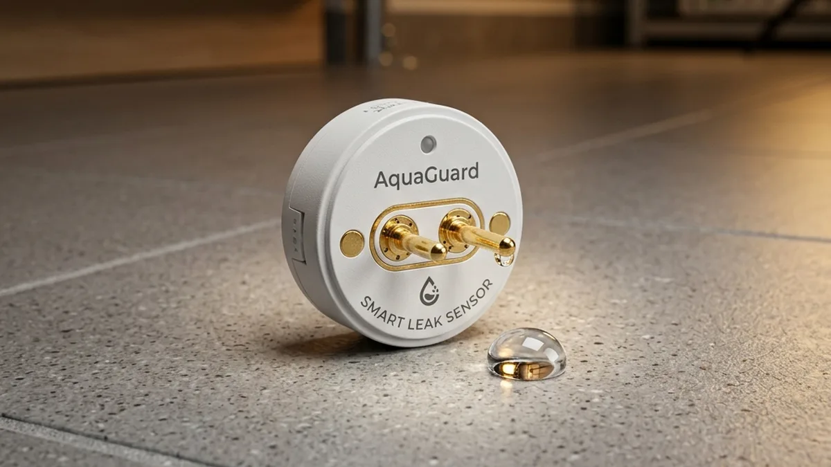
The vast majority of commercially available smart water leak sensors, including popular models from Aqara, Govee, Samsung SmartThings, and Fibaro, utilize a resistive sensing mechanism. This involves two or more conductive probes, often nickel-plated or gold-plated for corrosion resistance, positioned in close proximity. When a conductive liquid (water, particularly with dissolved minerals) bridges these probes, it significantly lowers the electrical resistance between them. The sensor’s embedded microcontroller (MCU) continuously monitors this resistance. Upon detecting a resistance value below a pre-programmed threshold (typically in the megaohms to kiloohms range, depending on sensitivity), the MCU triggers an alert.
While less common in consumer leak detection, capacitive sensing Offers an alternative. Capacitive sensors detect changes in capacitance, often by measuring the dielectric constant of the material between two conductive plates or traces. Water, having a high dielectric constant (εr ≈ 80), significantly alters the capacitance of the sensing element compared to air (εr ≈ 1). This method can potentially offer greater immunity to surface contamination and minor mineral deposits, as it doesn’t rely on direct electrical conduction, but it is more complex and costly to implement for wide-area floor detection.
For the scope of this deep dive, our focus remains on resistive sensors due to their prevalence and the specific false alarm mechanisms they engender.
1.2 Electrolytic Bridge Formation and Mineral Content
The core of the resistive sensor’s operation relies on water acting as an electrolyte. Pure H2O is a poor conductor of electricity. However, natural water sources (tap water, groundwater, condensation) invariably contain dissolved ions such as calcium (Ca2+), magnesium (Mg2+), sodium (Na+), potassium (K+), chlorides (Cl–), and sulfates (SO42-). These ions facilitate the movement of charge, making the water conductive. The higher the concentration of these dissolved solids – often referred to as “hard water” – the lower the electrical resistance, and thus, the more readily a sensor will trigger.
A “phantom drip” can occur when even a minuscule amount of moisture, perhaps from high ambient humidity condensing on a cold floor or subtle subsurface wicking, forms an electrolytic bridge between the probes. If this moisture is laden with minerals, its conductivity can easily exceed the sensor’s trigger threshold, signaling a leak where none exists.
1.3 Concrete Wicking, Hygroscopicity, and Substrate Conductivity
Concrete, a ubiquitous building material in basements and utility rooms, is inherently porous. This porosity allows for capillary action, where subsurface moisture can be drawn upwards to the surface. This phenomenon, known as moisture wicking, is particularly pronounced in high-humidity environments or when there is a high water table. Even if the concrete floor appears dry to the touch, microscopic films of moisture, often rich in dissolved salts from the concrete itself or from groundwater, can accumulate on the surface.
Furthermore, concrete can be hygroscopic, meaning it absorbs and retains moisture from the air. In a humid basement, concrete can absorb enough atmospheric water vapor to become subtly damp, creating a conductive path. When a leak sensor’s base, especially if it’s made of a slightly porous or non-perfectly sealed plastic, sits directly on this subtly damp, conductive concrete, the sensor’s probes can effectively become part of a larger, unintended circuit involving the floor itself. This creates a low-resistance pathway that bypasses the need for a visible puddle, triggering a false alarm.
1.4 Mineral Calcification and Biofilm Formation
Beyond immediate moisture, the long-term presence of even intermittent dampness can lead to mineral calcification. As water evaporates from the sensor’s probes or the surrounding floor, it leaves behind dissolved minerals. Over time, these minerals accumulate, forming a visible white or off-white crust that can permanently bridge the gap between the sensor’s contacts. This mineral bridge acts as a persistent low-resistance pathway, causing the sensor to continuously report a leak, even when the area is bone dry. This is especially common in areas prone to condensation or minor, unnoticed splashes that slowly evaporate.
Less frequently, but still a factor in persistently damp environments, is biofilm formation. Microorganisms, such as bacteria and fungi, can thrive in moist conditions, forming thin, slimy layers on surfaces. These biofilms, while not as inherently conductive as mineral deposits, can trap moisture and dissolved ions, contributing to the formation of a conductive bridge or enhancing the wicking effect, further exacerbating the false alarm problem.
Leak Sensor Reliability Flow – Advanced Diagnostics
+------------------------------------------+
| False Alarm Triggered (e.g., 02:00 AM)   |
+------------------------------------------+
                    |
                    v
+------------------------------------------+
| 1. Initial Verification & Local Env Scan |
|   (Visual inspection, humidity/temp,     |
|    floor resistivity)                    |
+------------------------------------------+
                    |
                    v
+------------------------------------------+
| 2. Probes & Casing Integrity Check       |
|   (Mineral buildup, water clinging,      |
|    capillary action)                     |
+------------------------------------------+
                    |
                    v
+------------------------------------------+
| 3. RF Link Health Assessment             |
|   (RSSI/LQI, "Offline" events,           |
|    co-channel interference)              |
+------------------------------------------+
                    |
                    v
+------------------------------------------+
| Diagnostic Path Complete: Stable         |
| Protection Achieved                      |
+------------------------------------------+
2. RF Link Budget and Interference Mitigation in Challenging Environments
While the primary cause of false positives often lies in the electro-physical interaction with water, a significant number of “phantom alerts” or, more accurately, communication failures and delayed alerts, stem from suboptimal wireless network performance. Water leak sensors are frequently deployed in challenging RF environments: Basements, utility closets, under metal sinks, or behind large appliances. These locations are often characterized by high material attenuation and significant electromagnetic interference (EMI).
2.1 The RF Landscape of IoT Protocols
Smart home leak sensors typically leverage one of several low-power wireless protocols:
- Zigbee (IEEE 802.15.4): Operates in the 2.4 GHz Industrial, Scientific, and Medical (ISM) band. Utilizes Direct Sequence Spread Spectrum (DSSS) for robustness against interference and supports mesh networking. Its 2.4 GHz frequency, however, is susceptible to interference from Wi-Fi, Bluetooth, and microwaves, and suffers significant attenuation from water, concrete, and metal.
- Z-Wave (ITU-T G.9959): Operates in sub-1 GHz frequencies (e.g., 908.42 MHz in North America, 868.42 MHz in Europe). This lower frequency band offers better penetration through walls and less interference from Wi-Fi. Z-Wave also employs mesh networking and is generally considered more robust for whole-home coverage, especially through structural elements.
- Thread (IEEE 802.15.4): Built on the same underlying radio technology as Zigbee (2.4 GHz ISM band) but uses IPv6 and is designed for robust, self-healing mesh networks. Shares similar RF characteristics and vulnerabilities to Zigbee regarding material attenuation.
- Bluetooth Low Energy (BLE): Utilizes 40 channels (2 MHz spacing) in the 2.4 GHz ISM band. BLE employs Adaptive Frequency Hopping (AFH) to dynamically avoid congested Wi-Fi channels and reserves three primary advertising channels (37, 38, 39) in the spectral gaps between Wi-Fi channels 1, 6, and 11 to minimize interference during discovery. While traditionally known for short-range, direct device-to-phone communication, Bluetooth Mesh networking extends its capabilities for wider-area coverage. However, its power consumption profile and typical implementation for sensors often prioritize local setup or periodic data logging over continuous, long-range, real-time leak detection compared to Zigbee or Z-Wave.
- Wi-Fi (IEEE 802.11 b/g/n): Operates in 2.4 GHz and 5 GHz bands. While offering high bandwidth, its power consumption is generally too high for battery-powered sensors requiring multi-year battery life, making it less common for leak detection (unless mains-powered). Wi-Fi sensors may suffer from similar 2.4 GHz interference issues as Zigbee/Thread.
2.2 The Faraday Cage Effect in Plumbing Zones
The placement of water leak sensors often puts them squarely within what can effectively become a localized Faraday cage. A Faraday cage is an enclosure used to block electromagnetic fields. In a typical utility room or under a sink, the combination of:
- Copper or steel piping: Extensive runs of metal pipes (water supply, drainage, HVAC lines) can act as highly reflective and absorptive surfaces for RF signals, especially at 2.4 GHz.
- Large metal appliances: Washing machines, dryers, water heaters, refrigerators, and furnace casings are substantial metal bodies that reflect, absorb, and scatter RF waves.
- Reinforced concrete walls/floors: The rebar within concrete significantly attenuates RF signals.
This environment leads to severe signal path loss And multipath fading. Multipath fading occurs when RF signals take multiple paths from transmitter to receiver (e.g., direct line-of-sight and reflected paths). These different paths can arrive out of phase, leading to destructive interference and significant drops in signal strength (RSSI – Received Signal Strength Indicator) at the receiver. This can cause sensors to frequently go “offline,” miss critical alerts, or drain batteries faster as they attempt to re-establish connections with higher transmit power.
2.3 Co-channel Interference and Adjacent Channel Interference
For Zigbee, Thread, and 2.4 GHz Wi-Fi sensors, the 2.4 GHz ISM band is a crowded RF spectrum. Your home’s Wi-Fi network, Bluetooth devices, cordless phones, microwave ovens, and even poorly shielded electronics can all emit signals in this band. This leads to:
- Co-channel Interference (CCI): When two or more devices transmit on the exact same frequency channel, their signals collide, leading to data corruption and packet loss. For example, a Wi-Fi router operating on channel 1 (center 2412 MHz, bandwidth 2401-2423 MHz) can significantly interfere with Zigbee channels 11-14 (2405-2420 MHz). It is crucial to note that Zigbee channel 26 (2480 MHz) is specifically designed to sit outside the primary 2.4 GHz Wi-Fi channels (1, 6, 11) and does not overlap with Wi-Fi channel 11 (2451-2473 MHz), making it a preferred choice for interference avoidance.
- Adjacent Channel Interference (ACI): When devices operate on closely spaced but not identical channels, their signals can still “bleed” into each other, causing noise and reducing effective throughput and range.
This interference manifests as increased latency in sensor reporting, missed heartbeat messages, and ultimately, sensors appearing offline or failing to report actual leaks or false positives reliably.
2.4 Link Budget Analysis and Network Topology Optimization
A rudimentary link budget analysis Helps understand signal reliability. It involves accounting for transmitted power (EIRP – Effective Isotropic Radiated Power), antenna gains, and all losses along the path (free-space path loss, material attenuation, interference). For battery-powered sensors, transmit power is often low to conserve energy.
To counteract RF challenges, network topology optimization is critical:
- Mains-Powered Repeaters/Routers: For Zigbee and Z-Wave networks, strategically placed mains-powered devices (e.g., smart plugs, light switches, dedicated repeaters) act as signal boosters and routing nodes. They extend the mesh network’s range and create alternative communication paths around obstacles. Placing one in the same room as a problematic leak sensor, ideally with a clear line of sight to the sensor and back to the hub, is often mandatory for robust connectivity.
- Channel Selection: For 2.4 GHz protocols, performing a Wi-Fi channel scan (using tools like NetSpot or WiFi Analyzer) to identify the least congested Wi-Fi channels (1, 6, 11) allows you to then select a Zigbee/Thread channel that minimizes overlap.
Primary Wi-Fi Channel Optimal Zigbee/Thread Channels Notes Channel 1 (2412 MHz) 20, 25, or 26 These channels fall outside Wi-Fi Channel 1’s main bandwidth. Channel 6 (2437 MHz) 25 or 26 Further away from Wi-Fi Channel 6. Channel 11 (2462 MHz) 11, 12, 13, 14, or 15 These Zigbee channels are below Wi-Fi Channel 11. General Recommendation Zigbee Channel 26 (2480 MHz) Often the most robust choice as it avoids all primary 2.4 GHz Wi-Fi channels.
3. Advanced Hardware and Firmware Diagnostics
Beyond external factors, the internal design and operational parameters of the sensor itself play a crucial role in its susceptibility to false alarms.
3.1 Sensor Architecture and Probe Design
The physical design of the sensor probes and their interface with the plastic casing are critical. Probes are typically made of stainless steel, often nickel-plated or, in higher-end models, gold-plated for superior corrosion resistance and conductivity. The spacing between probes is a fundamental design parameter that dictates sensitivity: Closer probes mean a smaller amount of water is needed to bridge the gap, increasing sensitivity but also potentially false positives.
The junction where probes meet the plastic housing is a common failure point. If not perfectly sealed, water can wick into the internal circuitry, leading to permanent damage or erratic readings. The geometry of the casing also matters; some designs feature raised probes or a hydrophobic coating on the surrounding plastic to prevent water from clinging to the casing and inadvertently bridging the contacts.
3.2 Firmware Thresholds and Sensitivity Calibration
Every resistive leak sensor contains an Analog-to-Digital Converter (ADC) that measures the resistance between its probes. The MCU then compares this measured resistance value against a pre-programmed digital threshold. If the resistance drops below this threshold, an alert is triggered. This threshold is set by the manufacturer during firmware development.
Consumer-grade sensors rarely offer user-adjustable sensitivity thresholds. This fixed threshold is a compromise: Sensitive enough to detect small leaks quickly, but not so sensitive that it’s constantly triggering on ambient moisture. Unfortunately, this “one-size-fits-all” approach can be problematic in highly humid environments or on porous concrete. An ideal sensor would allow dynamic adjustment of this threshold, perhaps even integrating environmental data (temperature, humidity) to adapt its sensitivity, though this is a feature typically found in industrial or high-end commercial systems, not standard smart home devices.
3.3 Power Management and Battery Voltage Fluctuation
Battery-powered sensors rely on stable voltage for accurate readings and reliable communication. While low battery is more commonly associated with communication dropouts (“offline” alerts) rather than false positives, significant voltage fluctuations or critically low battery levels can sometimes cause the internal ADC to provide inaccurate readings, potentially pushing a borderline resistance value over the alert threshold. Modern MCUs usually have built-in voltage regulators, but it’s a factor to consider in persistent, inexplicable false alarms.
3.4 Environmental Compensation (Hypothetical/Future Architectures)
As IoT sensor technology advances, future iterations of leak sensors could incorporate additional environmental sensors (e.g., temperature, relative humidity, atmospheric pressure) to implement intelligent environmental compensation. By continuously monitoring these parameters, the sensor’s firmware could dynamically adjust its conductivity threshold. For instance, in periods of high humidity and low temperature (conditions conducive to condensation and concrete wicking), the sensor might temporarily increase its resistance threshold to mitigate false positives, returning to a more sensitive setting under normal conditions. This advanced logic, while complex to implement in low-power devices, represents a promising direction for enhanced reliability.
4. Comprehensive Troubleshooting and Mitigation Strategies: A Step-by-Step Guide
Addressing false alarms requires a systematic approach that combines physical intervention, environmental control, and network optimization.
Step 1: Initial Assessment and Verification
Action: When a false alarm occurs, the immediate priority is to visually confirm the absence of an actual leak. Detail: Before dismissing it as a “phantom,” thoroughly inspect the area around the sensor. Use a flashlight to check for subtle puddles, damp spots, or condensation. Check nearby pipes, appliances, and walls for any signs of leakage. If no visible water is present, proceed to the next steps.
Step 2: Physical Sensor Inspection and Cleaning
Action: Clean the sensor probes and inspect the casing. Detail:
- Power Down: If possible, temporarily remove the battery from the sensor to prevent accidental triggers during cleaning.
- Visual Inspection: Examine the metal probes for any white, green, or dark mineral deposits, corrosion, or debris. Also, check the plastic casing around the probes for water marks or clinging moisture.
- Cleaning Procedure:
- Dampen a clean microfiber cloth or cotton swab with 90%+ isopropyl alcohol (IPA). Avoid lower concentrations as they contain more water which can leave residue.
- Gently but thoroughly scrub the metal probes to remove all visible calcification and grime. The IPA helps dissolve mineral salts and evaporates quickly without leaving conductive residue.
- Clean the immediate surrounding plastic casing, ensuring no residue remains that could wick moisture.
- For stubborn deposits, a soft-bristle brush (like a toothbrush) or a non-abrasive plastic scraper can be used very gently to dislodge calcification, followed by an IPA wipe.
- Dry Thoroughly: Ensure the sensor is completely dry before reinserting the battery.
Step 3: Isolation from Substrate (The Shim Method)
Action: Elevate the sensor body from direct contact with the floor. Detail:
- Purpose: This step is critical for breaking the capillary action and direct conductive path between porous concrete/subfloor and the sensor’s body. By elevating the sensor, only the very tips of the probes are exposed to potential water, preventing moisture wicking along the sensor’s base.
- Material: Use a thin, non-conductive, water-impermeable material. Excellent choices include:
- A credit card or gift card cut to size.
- A piece of thin acrylic or polycarbonate sheet.
- A segment of a plastic report cover.
- Avoid cardboard or wood, as these can absorb moisture themselves.
- Implementation:
- Place the chosen shim directly under the sensor.
- Ensure the shim is large enough to support the entire base of the sensor, preventing any part of the sensor’s plastic casing from touching the floor.
- Crucially, the shim must have an opening or be shaped such that the metal probes still make direct contact with the floor surface. Some users cut a small ‘U’ shape or two small holes for the probes to pass through.
- Secure Placement: Ensure the sensor is stable on the shim and won’t easily be dislodged.
Step 4: Environmental Control and Management
Action: Reduce ambient humidity and improve air circulation. Detail:
- Dehumidification: In basements or utility rooms with high relative humidity (>50-60%), a dehumidifier is an invaluable tool. It reduces the moisture content in the air, thereby reducing condensation and the rate of concrete wicking.
- Ventilation: Ensure adequate airflow around the sensor’s location. Stagnant, humid air is more likely to cause condensation. Consider a small fan in enclosed spaces if practical.
- Temperature Stability: Minimize drastic temperature swings, which can lead to condensation on cold surfaces.
Step 5: RF Network Diagnostics and Optimization
Action: Improve wireless signal reliability and mitigate interference. Detail:
- Hub/Gateway Placement: Ensure your smart home hub or gateway is centrally located and not surrounded by dense materials or large metal objects.
- Add Repeaters/Routers:
- For Zigbee/Z-Wave, deploy mains-powered devices (smart plugs, light switches, dedicated repeaters) strategically. Place one in the same room or an adjacent room to the problematic sensor, ensuring it’s not obstructed by metal or thick walls.
- These devices not only extend range but also provide alternative routing paths, making the mesh network more robust against localized interference.
- Channel Optimization (for 2.4 GHz protocols):
- Use a Wi-Fi analyzer tool (e.g., on a smartphone or laptop) to identify the least congested Wi-Fi channels (1, 6, 11).
- Adjust your Wi-Fi router’s channel to one of these non-overlapping options.
- Consult your smart home hub’s documentation to see if you can manually select the Zigbee/Thread channel. Choose a channel that minimizes overlap with your primary Wi-Fi channel.
Primary Wi-Fi Channel Optimal Zigbee/Thread Channels Notes Channel 1 (2412 MHz) 20, 25, or 26 These channels fall outside Wi-Fi Channel 1’s main bandwidth. Channel 6 (2437 MHz) 25 or 26 Further away from Wi-Fi Channel 6. Channel 11 (2462 MHz) 11, 12, 13, 14, or 15 These Zigbee channels are below Wi-Fi Channel 11. General Recommendation Zigbee Channel 26 (2480 MHz) Often the most robust choice as it avoids all primary 2.4 GHz Wi-Fi channels.
- RSSI Monitoring: If your smart home platform or hub provides diagnostic tools, monitor the Received Signal Strength Indicator (RSSI) or Link Quality Indicator (LQI) for the sensor. An RSSI below -80 dBm or a consistently low LQI indicates a weak connection that needs improvement.
Step 6: Advanced Hardware Protection (Silicone Grease)
Action: Apply a hydrophobic barrier to the non-contact plastic areas. Detail:
- Purpose: This technique is for sensors in extremely high-humidity or splash-prone environments where water might wick along the plastic casing and bridge the probes from above or the sides.
- Material: Use a small amount of dielectric silicone grease (e.g., plumber’s grease, silicone O-ring grease). This material is non-conductive and highly hydrophobic, repelling water.
- Application:
- After cleaning (Step 2) and with the battery removed, apply a very thin film of silicone grease to the plastic surfaces of the sensor base, specifically the areas immediately adjacent to the metal probes, but ensuring no grease gets directly on the conductive probe surfaces themselves.
- The goal is to create a water-repellent barrier that forces any moisture to bead up and run off, preventing it from forming a continuous film that could bridge the probes.
- Caution: Use sparingly and carefully. Contaminating the probes with grease will render the sensor inoperative.
Step 7: Firmware/App-level Adjustments (If Available)
Action: Check sensor-specific settings within your smart home app. Detail: While rare for basic leak sensors, some advanced models or professional systems may offer options within their companion app or hub interface to adjust sensitivity thresholds, debounce timers (how long water must be present before an alert), or reporting intervals. Consult your sensor’s manual or app settings for any such configurable parameters.
Step 8: Sensor Relocation or Alternative Sensor Types
Action: If all previous steps fail, consider moving the sensor or trying a different type. Detail:
- Relocation: If a specific spot consistently triggers false alarms despite all mitigations, consider moving the sensor slightly to a less problematic area, even if it’s just a few inches away from a wall or a particularly porous patch of concrete.
- External Probes: Some sensors (e.g., Fibaro Flood Sensor) offer the option to connect external wired probes. This allows the main sensor body to be placed in a drier, more RF-friendly location, while only the small, external probes are positioned on the floor. This completely isolates the main unit from floor-based wicking.
- Alternative Technologies: For critical areas, consider commercial-grade sensors or alternative detection methods (e.g., rope-style leak detectors that cover a larger area and can be less prone to localized single-point false positives).
5. Comparative Analysis: Sensor Types and Reliability Factors
| Feature | Aqara Water Leak Sensor | Govee WiFi Water Leak Detector | Moen Flo Smart Water Detector | Fibaro Flood Sensor (Z-Wave/Zigbee) | Samsung SmartThings Water Leak Sensor |
|---|---|---|---|---|---|
| Connectivity Protocol | Zigbee 3.0 | Wi-Fi (2.4 GHz) | Wi-Fi (2.4 GHz) | Z-Wave or Zigbee | Zigbee |
| Power Source | CR2032 (up to 5 years) | AAA x 2 (up to 2 years) | AAA x 2 (up to 2 years) | CR123A (up to 2.5 years) | CR2 (up to 3 years) |
| Detection Method | Resistive Probes | Resistive Probes | Resistive Probes (front & bottom) | Resistive Probes (internal & external) | Resistive Probes |
| Known False Alarm Tendencies | High sensitivity to concrete wicking, mineral buildup. | Moderate sensitivity to concrete wicking, Wi-Fi congestion. | Moderate sensitivity to concrete wicking, Wi-Fi congestion. | Lower due to external probe option, but internal still susceptible. | High sensitivity to concrete wicking, mineral buildup. |
| Unique Features | Compact, integrated temperature sensor. | Integrated siren, app notifications without hub. | Integrated siren, top & bottom detection, temperature & humidity. | External wired probe option, temperature sensor, tilt sensor, integrated siren. | Compact, integrated temperature sensor. |
| Mitigation Notes | Shim + cleaning essential. Zigbee mesh optimization. | Shim + cleaning. Strong Wi-Fi signal coverage crucial. | Shim + cleaning. Strong Wi-Fi signal coverage crucial. | Utilize external probe for floor detection. Z-Wave/Zigbee mesh optimization. | Shim + cleaning essential. Zigbee mesh optimization. |
6. Frequently Asked Questions (FAQ)
Why do false alarms occur more frequently during summer or high-humidity periods?
False alarms increase during warmer, more humid periods primarily due to increased moisture content in the air and within porous materials like concrete. High ambient humidity leads to greater condensation on cool surfaces (like basement floors or pipes). More critically, concrete’s hygroscopic nature causes it to absorb more moisture from the air, increasing its surface conductivity through capillary action and dissolved salts. This elevated moisture creates a more persistent, subtle conductive path between the sensor probes, even without a visible puddle.
Can I adjust my smart water leak sensor’s sensitivity?
For most consumer-grade smart water leak sensors, direct user-adjustable sensitivity settings are not available. Manufacturers pre-program a fixed conductivity threshold in the sensor’s firmware to balance detection capability with false alarm immunity for a general use case. Some advanced or professional-grade systems might offer this feature, but it’s rare in off-the-shelf smart home devices. The mitigation strategies outlined in this guide (physical isolation, cleaning, environmental control) are designed to compensate for this fixed sensitivity.
What is the best material for a sensor shim?
The best material for a sensor shim is any thin, rigid, non-conductive, and water-impermeable plastic. Excellent choices include cut pieces of credit cards, gift cards, plastic report covers, or thin acrylic/polycarbonate sheets. The key properties are that it must not absorb water, must not conduct electricity, and must be rigid enough to provide stable elevation for the sensor while allowing the probes to reach the floor. Avoid porous materials like cardboard or wood, which can absorb moisture and defeat the purpose.
How often should I clean my water leak sensors?
The frequency of cleaning depends on the sensor’s environment. For sensors in low-humidity, clean areas, an annual cleaning with 90%+ isopropyl alcohol (IPA) might suffice. However, for sensors in high-humidity basements, near sump pumps, or in areas prone to condensation and hard water deposits, a prophylactic cleaning every 3 to 6 months is highly recommended. Regular visual inspection of the probes can also help determine if more frequent cleaning is necessary.
Do Wi-Fi-based leak sensors have different false alarm issues compared to Zigbee or Z-Wave?
The fundamental false alarm mechanisms related to water conductivity (concrete wicking, mineral calcification) are identical across all resistive sensor types, regardless of their wireless protocol. However, Wi-Fi sensors may experience different types of communication issues due to Wi-Fi’s higher power consumption (leading to shorter battery life if not mains-powered) and its susceptibility to congestion in the 2.4 GHz band. While a Wi-Fi sensor might not falsely detect water differently, its ability to report that detection reliably can be impacted by network performance unique to Wi-Fi, potentially leading to missed alerts or delayed notifications, which can be just as problematic as false positives.
What is the difference between resistive and capacitive water leak sensors?
Resistive sensors Detect water by measuring the electrical resistance between two or more exposed metal probes. When conductive water bridges the probes, the resistance drops below a threshold, triggering an alert. They are simple, inexpensive, and widely used, but susceptible to mineral buildup and surface conductivity from porous materials. Capacitive sensors, on the other hand, detect changes in capacitance caused by the presence of water (which has a high dielectric constant). They typically have no exposed metal contacts, making them less prone to issues like corrosion or mineral bridging, but they are generally more complex and costly to manufacture for broad-area leak detection.
Conclusion
The “phantom drip” is more than a minor annoyance; it erodes trust in smart home automation, potentially leading users to disable critical safety features. By understanding the intricate interplay of electro-physical principles, environmental factors, and wireless communication dynamics, we can transform these seemingly temperamental devices into reliable sentinels. The solutions, though requiring a technical understanding, are often straightforward: Meticulous cleaning of probes, strategic physical isolation of the sensor body, proactive environmental management, and robust RF network optimization. As IoT architects, our goal is to design systems that are not just smart, but consistently dependable. Implementing these advanced diagnostic and mitigation strategies will ensure your smart water leak sensors provide unwavering protection, truly eliminating the phantom drip and delivering peace of mind.
About these guides
These guides are compiled and maintained by the Smart Home Expert editorial desk. Each one is built from manufacturer documentation and the published Zigbee, Z-Wave, Thread and Wi-Fi specifications, then written up as a diagnostic sequence you can follow in order. Found something that does not match your hardware? Tell us and we will correct the sheet.
Specifications and references
The primary documentation for the protocols and products discussed above. Where this guide gives a figure — a frequency, a voltage, a timeout — these are where it comes from.