Thermostat Says Delayed or E74? HVAC Sync Faults Explained
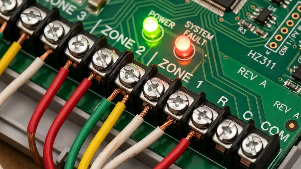
Countless smart home devices promise seamless integration. The smart thermostat, however, stands alone in its critical function. When it malfunctions, it’s not just an inconvenience; it can render your living space uninhabitable, disrupting essential climate control. In the large majority of cases where a smart thermostat fails to command an HVAC system are not due to inherent hardware defects, but rather intricate communication breakdowns – be it power delivery inconsistencies, protocol synchronization errors, or misconfigured network parameters. This guide will transcend basic troubleshooting, delving into the technical underpinnings necessary to diagnose and rectify these complex sync issues.
Diagnostic Loop Initiation
Check furnace/air handler breaker and control board LED status.
Target Range: 24V – 28V AC (RMS)
My evaluations of dozens of smart thermostat models, from the sophisticated Nest Learning Thermostat And Ecobee SmartThermostat to more budget-friendly Wyze Thermostats, consistently highlight a fundamental disparity: The “plug and play” marketing often collides with the reality of diverse, sometimes decades-old, HVAC system architectures. Whether you’re grappling with a heat pump that refuses to engage its reversing valve or an air conditioner that cycles erratically, the following systematic methodology will equip you with the advanced knowledge required to diagnose and rectify these persistent synchronization anomalies.
The Invisible Handshake: Deep Dive into Thermostat-HVAC Communication Protocols and Power Management
The operational nexus between your smart thermostat and HVAC system is a meticulously engineered interplay of low-voltage electrical signals and, for smart thermostats, sophisticated wireless network protocols. Understanding these layers is paramount to advanced troubleshooting.
24V AC Control Circuitry: The Wired Backbone
At its core, all residential HVAC control relies on a 24V Alternating Current (AC) circuit. This low-voltage system is designed for safety and reliability, utilizing a step-down transformer typically located within the furnace or air handler. The common wiring schema includes:
| Terminal Designation | Typical Wire Color | Primary Function | Technical Notes |
|---|---|---|---|
| R (Rh/Rc) | Red | 24V AC Hot Power | Provides continuous 24V AC. Rh for heating, Rc for cooling. Jumper often needed if only one R wire. |
| C (Common) | Blue/Black | 24V AC Return Path | Completes the 24V AC circuit, crucial for continuous power to smart thermostats (Wi-Fi/Zigbee). |
| W (W1) | White | Call for Heat | Thermostat closes R-W relay to signal furnace to initiate heating cycle. |
| Y (Y1) | Yellow | Call for Cool | Thermostat closes R-Y relay to signal air conditioner compressor to turn on. |
| G | Green | Call for Fan | Thermostat closes R-G relay to activate indoor blower fan independently. |
| O/B | Orange/Brown | Reversing Valve (Heat Pumps) | Switches heat pump between heating and cooling modes. O (cooling) or B (heating) depends on manufacturer. |
The thermostat essentially acts as a set of low-current relays, selectively connecting the R wire to W, Y, G, or O/B to trigger corresponding relays on the HVAC control board. These larger relays then switch the high-voltage (120V/240V AC) power to activate the furnace, compressor, or fan motor.
Power Stealing vs. Dedicated C-Wire: A Critical Distinction
Many older HVAC systems (and some newer, simpler ones) lack a dedicated C-wire. To operate, smart thermostats without a C-wire resort to “power stealing” or “power harvesting.” This mechanism involves drawing tiny amounts of current through the control wires (W, Y, G) during cycles when they are not actively commanding the HVAC system. The thermostat uses this minute current to charge an internal battery or capacitor bank. During active heating or cooling cycles, when a constant current flow would trigger the HVAC, the thermostat briefly ceases drawing power or switches to battery power.
While ingenious, power stealing has severe limitations:
- Intermittent Power: The thermostat’s internal battery/capacitor may not charge sufficiently during short idle periods.
- Voltage Drop: The parasitic current draw can cause a slight voltage drop on the control lines, potentially preventing the HVAC control board’s sensitive relays from reliably engaging. A 2V drop from 24V AC can be enough to cause intermittent failures.
- Wi-Fi/Zigbee Instability: Wireless communication modules are power-hungry. Insufficient or fluctuating power often manifests as Wi-Fi disconnections, slow response times, or complete network dropouts, directly impacting cloud-based control and synchronization. This is particularly prevalent in Nest Devices, leading to “Low Power” warnings and error codes like N260.
The installation of a Power Extender Kit (PEK) or similar C-wire adapter is a robust solution. These kits typically use a small module at the HVAC control board to create a C-wire connection by repurposing one of the existing wires (e.g., G wire for fan) or by intelligently routing power. This provides a stable, continuous 24V AC supply, eliminating power-related sync issues and ensuring reliable wireless operation.
Wireless Communication Protocols: The Digital Overlay
Smart thermostats leverage various wireless protocols for local control, remote access, and integration into broader smart home ecosystems.
Wi-Fi (IEEE 802.11 b/g/n, 2.4 GHz)
Most smart thermostats, including many Nest And Ecobee Models, primarily use Wi-Fi for connectivity. This allows direct communication with your home router and, subsequently, to cloud services for remote control, firmware updates, and data analytics.
- RF Characteristics: Operates in the 2.4 GHz ISM band. Susceptible to interference from other 2.4 GHz devices (microwaves, cordless phones, Bluetooth, neighboring Wi-Fi networks). Signal strength (RSSI) is critical; an RSSI below -70 dBm often leads to unstable connections.
- TCP/IP Stack: Thermostats implement a full TCP/IP stack to communicate over your network. They typically use DHCP for IP address assignment and DNS for resolving cloud service hostnames.
- mDNS/Bonjour: Used for local network discovery of the thermostat by mobile apps or other smart home hubs, enabling initial setup and local control without requiring cloud access for basic functions.
- Cloud Dependency: While local control is often possible, most advanced features (scheduling, geofencing, remote access) rely on a stable connection to the manufacturer’s cloud servers. Packet loss or high latency to these servers can manifest as sync delays or “not responding” messages.
Zigbee & Thread (IEEE 802.15.4)
Some thermostats, particularly newer Nest Models (e.g., Nest Thermostat E, Nest Learning Thermostat 3rd Gen) and devices supporting Matter, incorporate Zigbee (IEEE 802.15.4) or Thread (built on 802.15.4) for local mesh networking. These protocols offer:
- Mesh Topology: Devices can relay messages for each other, extending network range and improving robustness.
- Low Power Consumption: Designed for battery-powered devices, though smart thermostats are typically line-powered.
- RF Characteristics: Also operates in the 2.4 GHz band, meaning it can interfere with Wi-Fi on overlapping channels. Careful channel selection is crucial to minimize co-existence issues. While Wi-Fi channels 1, 6, and 11 are non-overlapping for Wi-Fi, Zigbee channels 15 and 20 significantly overlap with Wi-Fi channels 6 and 11 respectively. For optimal co-existence, consider using Zigbee channels 11, 25, or 26, which offer better separation from common Wi-Fi channels. Zigbee channels 25 and 26 are particularly robust choices as they fall entirely outside the primary Wi-Fi 1, 6, and 11 spectrums.
- Local Control: Often allows for more robust local control via a compatible hub (e.g., Nest Hub, Apple HomePod Mini for Thread) even if internet connectivity is lost.
Bluetooth Low Energy (BLE)
Bluetooth Low Energy (BLE) is a distinct protocol from Classic Bluetooth, optimized for low power consumption. It utilizes 40 channels (2 MHz spacing) in the 2.4 GHz ISM band, unlike Classic Bluetooth’s 79 channels. BLE employs Adaptive Frequency Hopping (AFH) to dynamically avoid congested Wi-Fi channels, and has 3 dedicated advertising channels (channels 37, 38, 39) strategically placed in the spectral gaps between Wi-Fi channels 1, 6, and 11 to minimize interference during device discovery and connection establishment. BLE is commonly used for initial setup and provisioning (e.g., pairing the thermostat with your smartphone app) or for proximity-based features. It’s generally not used for continuous operational communication with the HVAC system or cloud.
Clock Drift and Packet Synchronization Errors
Modern smart homes rely on precise timing. Thermostat schedules, geofencing triggers, and even HVAC safety lockouts are time-dependent. Clock drift (where a device’s internal clock slowly deviates from actual time) can lead to commands being sent at the wrong moment. Smart thermostats typically use Network Time Protocol (NTP) to synchronize with internet time servers. If network connectivity is intermittent or unstable, NTP updates can fail, leading to:
- Incorrect Scheduling: Thermostat executes programs at the wrong time.
- Cloud Sync Issues: Discrepancies between the thermostat’s perceived time and the cloud server’s time can cause commands to be rejected or delayed.
- Event Log Mismatches: Diagnostic logs become unreliable.
Packet synchronization errors occur when data packets are lost or corrupted during transmission over Wi-Fi or Zigbee. This can be due to RF interference, poor signal strength, or network congestion, leading to delayed or missed commands to the HVAC system.
| Error Code/Symptom | Brand/Context | Meaning & Root Cause Analysis | Priority Fix & Technical Rationale |
|---|---|---|---|
| E74 | Nest | No power to Rh wire. Indicates a complete loss of 24V AC power on the heating circuit. Often due to tripped HVAC circuit breaker, blown internal fuse on HVAC control board, or a faulty step-down transformer. | Immediate Action: Verify circuit breaker. Inspect furnace/air handler control board for blown fuses (often a 3-amp automotive-style fuse) and 24V AC transformer output with a multimeter. Check continuity of Rh wire. |
| N260 / “Low Power” | Nest | C-wire required / Insufficient power. Thermostat’s internal battery/capacitor is depleting faster than it can recharge via power stealing, often exacerbated by Wi-Fi module power draw. | Mandatory Upgrade: Install a Power Extender Kit (PEK) or run a dedicated C-wire. This provides continuous 24V AC, stabilizing power delivery and ensuring reliable Wi-Fi/Zigbee operation. |
| H1/C1 | Wyze Thermostat | Relay Timeout. The thermostat sent a command (e.g., to activate heat) but did not detect a change in HVAC system status (e.g., current draw, temperature differential) within an expected timeframe. This can indicate a physical wiring issue, a stuck HVAC relay, or a safety lockout. | Systematic Check: Re-seat R and C wires at both thermostat and HVAC control board. Manually jump R to W (for heat) or R to Y (for cool) at the HVAC board to test if the HVAC responds directly. If it does, the issue is thermostat-side or wiring to thermostat. |
| “Delayed” / “Waiting” | Most Smart Thermostats | Compressor Short Cycle Protection. The HVAC system’s internal control board has engaged a safety lockout, typically 5 minutes (300 seconds), to protect the compressor from damage due to rapid on/off cycling. | Patient Observation: Wait the full 300 seconds (5 minutes) before attempting further diagnostics or sending new commands. This is a normal and necessary safety feature. |
| Intermittent Wi-Fi Disconnects | All Wi-Fi Smart Thermostats | RF Interference / Weak Signal / Power Instability. The 2.4 GHz Wi-Fi signal is being degraded by other devices, physical obstructions, or the thermostat is experiencing power fluctuations (often due to power stealing). | Network Optimization: Use a Wi-Fi analyzer app to identify congested channels. Adjust router channel if necessary. Ensure thermostat RSSI is above -65 dBm. If power stealing, install a C-wire or PEK. Check for AP isolation settings on router. |
Common Causes of Sync Failure: A Deeper Dive
HVAC Safety Mechanisms and Interlocks
Modern HVAC systems are equipped with numerous safety switches designed to prevent damage to expensive components and ensure safe operation. When triggered, these switches often interrupt the 24V AC control circuit, preventing the furnace or AC from running, even if the thermostat is correctly sending commands.
- Condensate Overflow Float Switch: Located in the drain pan or condensate line of the indoor coil (AC or high-efficiency furnace). If the drain clogs and water accumulates, the float rises, opening a circuit (often the Y-wire circuit) to prevent water damage. Pro Tip: Inspect the drain pan for standing water and clear any blockages.
- Pressure Switches (High/Low): Found in refrigerant lines of AC units and heat pumps. They trip if refrigerant pressure is outside operating parameters, indicating a leak, overcharge, or restricted flow.
- Limit Switches (Furnace): Prevents overheating. If the furnace heat exchanger gets too hot (e.g., due to a dirty filter or blocked vents), the limit switch opens, shutting off the burner.
- Flame Rollout Switch (Furnace): A safety device that trips if flames escape the combustion chamber.
- Blower Door Safety Switch: Ensures the furnace/air handler access panel is securely closed before allowing operation.
When one of these safeties trips, it creates an open circuit, effectively cutting the 24V AC signal path from the thermostat to the relevant HVAC component. The thermostat, unable to sense the expected current draw or response, will report a “not responding” error.
Relay Delays and Compressor Short Cycling Protection
As mentioned, HVAC compressors are delicate machines. Rapid cycling (turning on and off too quickly) can cause significant wear and tear, leading to premature failure. To mitigate this, virtually all modern HVAC control boards incorporate a minimum off-time delay, typically 5 minutes (300 seconds). If you issue an “off” command and then an “on” command for cooling or heating within this window, the HVAC system will intelligently ignore the second command until the delay expires. Your smart thermostat will usually display a message like “Delayed” or “Waiting for HVAC.” It is absolutely critical to wait the full 300 seconds before assuming a fault. Bypassing this safety can void warranties and damage your compressor.
Step-by-Step Advanced Troubleshooting
This systematic approach will guide you through diagnosing complex sync issues, moving from fundamental power checks to advanced network and component-level diagnostics.
Step 1: The Terminal & Voltage Integrity Check
This is the bedrock of low-voltage HVAC diagnostics. Power issues account for a significant percentage of “not responding” errors.
- De-energize HVAC: Crucially, switch off the main power to your furnace or air handler at the circuit breaker. This is for your safety and to prevent accidental short circuits during wire manipulation.
- Remove Thermostat: Carefully pull the thermostat display unit off its baseplate.
- Visual Inspection: Examine the wires connected to the thermostat baseplate. Ensure they are securely seated in their terminals, with no frayed strands or corrosion. Loose connections are notorious for intermittent faults.
- Re-energize HVAC: Turn the circuit breaker back on.
- Voltage Measurement (R to C):
- Set your multimeter to measure Alternating Current (AC) Voltage, typically in the 0-200V AC range.
- Place one probe on the ‘R’ terminal (or Rh/Rc if separated) and the other probe on the ‘C’ (Common) terminal.
- Expected Reading: You should consistently measure between 24V AC and 28V AC (RMS).
- Diagnosis:
- < 20V AC: Indicates a significant power delivery problem. This could be a failing HVAC transformer, a blown fuse on the control board, a severely undersized transformer, or excessive current draw from the thermostat (common with power-stealing smart thermostats).
- 0V AC: Complete loss of power. Re-check circuit breaker, furnace door safety switch, and internal HVAC board fuse.
- Fluctuating Voltage: Suggests an intermittent connection or an overloaded transformer struggling to maintain output.
- Voltage Measurement (R to W, R to Y, R to G – During Call):
- With the thermostat re-mounted and powered, initiate a call for heat (R to W), cool (R to Y), or fan (R to G) from the thermostat’s interface.
- While the call is active, measure the voltage between R and the respective terminal (W, Y, or G).
- Expected Reading: You should measure approximately 0V AC (or very close to it, typically < 0.5V AC) between R and the actively called terminal. This indicates the thermostat’s internal relay has successfully closed, creating a short circuit path for the 24V AC to flow to the HVAC control board.
- Diagnosis:
- ~24V AC still present: The thermostat’s internal relay for that specific function is failing to close, or the command isn’t being registered internally. This points to a thermostat hardware fault.
Step 2: HVAC Control Board Diagnostics & Manual Override
This step isolates whether the issue lies with the thermostat, its wiring, or the HVAC system itself.
- De-energize HVAC: Turn off power at the circuit breaker.
- Access Control Board: Locate the low-voltage terminal block on your furnace or air handler control board. Note the wire colors and their corresponding terminals. Take a photo for reference.
- Inspect Fuses & LEDs:
- Many HVAC control boards have a 3-amp automotive blade fuse. Visually inspect it for a broken filament. Replace if necessary.
- Observe the diagnostic LED on the control board. It often blinks in a specific pattern to indicate error codes. Consult your HVAC unit’s manual for the meaning of these flash codes.
- Manual HVAC Activation (Bypassing Thermostat):
- With power still off, carefully disconnect the thermostat wires from the low-voltage terminals on the HVAC control board. Ensure no bare wires touch.
- Re-energize HVAC.
- To test Heat: Using a short, insulated jumper wire (e.g., a paperclip with insulation, or a dedicated jumper), momentarily connect the ‘R’ terminal to the ‘W’ terminal on the HVAC control board. The furnace should ignite and the blower fan should engage after its pre-purge cycle.
- To test Cool: Momentarily connect ‘R’ to ‘Y’ and ‘R’ to ‘G’ (to activate both compressor and indoor fan). The outdoor compressor and indoor blower should start.
- To test Fan Only: Momentarily connect ‘R’ to ‘G’. The indoor blower fan should start.
- Diagnosis:
- HVAC Responds: If the HVAC system activates correctly with manual jumping, the problem is either with your thermostat unit, its wiring to the HVAC board, or a signal integrity issue (e.g., voltage drop due to power stealing).
- HVAC Does NOT Respond: The issue is deeper within the HVAC system, likely a tripped safety switch (float switch, limit switch), a faulty control board, or a failing component (e.g., contactor, motor). At this point, if you’ve checked fuses and safeties, it’s often time to call a professional HVAC technician.
- De-energize HVAC Before reconnecting thermostat wires.
Step 3: Equipment Re-detection & Wireless Network Diagnostics
Once wired integrity is confirmed, focus on the thermostat’s internal configuration and its network health.
- Thermostat Equipment Re-detection (Exact App Paths):
- Nest: On the thermostat itself or in the Nest app: Navigate to Settings > Equipment > Wiring Info. Ensure all physically connected wires are highlighted in green, indicating successful detection. If a wire isn’t detected, re-check physical connection.
- Ecobee: On the thermostat or in the Ecobee app: Go to Main Menu > Settings > Installation Settings > Test System. This allows you to manually trigger individual HVAC components (Fan, Heat, Cool) and verify their response.
- Wyze: In the Wyze app: Navigate to Thermostat Settings > Advanced > HVAC Info. There should be an option to “Refresh hardware handshake” or “Re-detect wires.” Confirm all wires are correctly identified.
If the thermostat cannot detect a wire that is physically connected and receiving 24V AC (verified in Step 1), it may indicate a faulty thermostat baseplate or internal logic.
- Wireless Network Diagnostics (for Wi-Fi thermostats):
- Signal Strength (RSSI): Most smart thermostats display their Wi-Fi signal strength (often in dBm) in their network settings. A value better than -65 dBm is ideal; -70 dBm or worse indicates a weak signal prone to disconnections.
- Wi-Fi Analyzer App: Use a smartphone app (e.g., Wi-Fi Analyzer by farproc for Android, or Airport Utility for iOS with Wi-Fi scanning enabled) to visualize Wi-Fi networks in your area.
- Identify your thermostat’s channel (2.4 GHz).
- Look for overlapping channels or strong interference from neighboring networks.
- Consider changing your router’s 2.4 GHz channel to 1, 6, or 11 (the non-overlapping channels) if congestion is high.
- Router Settings:
- AP Isolation / Client Isolation: Ensure this feature is disabled on your router. It prevents devices on the same Wi-Fi network from communicating with each other, which can block local control or discovery.
- Band Steering: If your router combines 2.4 GHz and 5 GHz networks under one SSID, try temporarily disabling band steering or creating separate SSIDs for each band to force the thermostat onto 2.4 GHz.
- Firewall Rules: Verify no outbound connections from the thermostat are blocked. Refer to your thermostat manufacturer’s documentation for required ports/IPs for cloud communication.
Architectural Overview: Smart Thermostat Ecosystem
+---------------------+           +---------------------+           +---------------------+
|                     |           |                     |           |                     |
|  Smart Thermostat   |           |    Home Wi-Fi Router    |           |    Cloud Services     |
| (e.g., Nest, Ecobee)|           | (2.4GHz Wi-Fi AP)   |           | (Manufacturer's Backend)  |
|                     |           |                     |           |                     |
| - Microcontroller   | | - DHCP Server       |  | - API Endpoints     |
| - Wi-Fi/Zigbee Radio|   Wi-Fi   | - DNS Resolver      |   Internet| - Data Storage      |
| - Relays (R-W, R-Y) | (IEEE 802.11)| - Firewall/NAT      | (TCP/IP, HTTP/S)| - Firmware Updates  |
| - Temperature/Humidity|           |                     |           | - Remote Control    |
|   Sensors           |           |                     |           |                     |
+----------^----------+           +----------^----------+           +----------^----------+
           | 24V AC Control Wiring (R, C, W, Y, G, O/B) |                      ^
           |                                            |                      |
           |                                            |                      |
           v                                            v                      |
+----------+-----------------------+           +---------------------+      +---------------------+
|                                  |           |                     |      |                     |
|    HVAC Control Board            |           |    Mobile App         |      |    Voice Assistant    |
| (Furnace/Air Handler/Heat Pump)  |           | (Smartphone/Tablet) |      | (e.g., Google Home, Alexa) |
|                                  |           |                     |      |                     |
| - 24V AC Transformer             |  | - API Integration   |
| - Relays (Fan, Heat, Cool)       |   Local Network (mDNS/Bonjour) / Cloud API | - Command Parsing   |
| - Diagnostic LEDs                |                                          |                     |
| - Safety Switches (Float, Limit) |                                          |                     |
+----------------------------------+                                          +---------------------+
Comprehensive FAQ Section
Q1: My Nest thermostat shows “No Power to Rh wire” (E74 error). What’s the most common cause, and how do I test it safely?
A1: The E74 error specifically indicates that the Nest thermostat is not detecting 24V AC on the Rh (Red, Heating Power) wire, which is the primary power source for heating calls. The most common causes are a tripped circuit breaker for your HVAC system, a blown low-voltage fuse on your furnace/air handler’s control board, or a failing 24V AC transformer within the HVAC unit. Less commonly, it could be a break in the Rh wire itself or a loose connection.
Safe Testing Procedure:
- Safety First: Turn off the main power to your HVAC system at the circuit breaker. This is paramount.
- Access HVAC Control Board: Open the access panel of your furnace or air handler. Locate the low-voltage terminal block where the thermostat wires connect.
- Inspect Fuse: Many control boards have a small 3-amp automotive-style fuse. Visually inspect the filament; if it’s broken, replace it with an identical fuse.
- Check Transformer Output: If the fuse is good, re-energize the HVAC system (turn the circuit breaker back on). Set your multimeter to AC Voltage (range 0-200V AC). Place the probes on the “R” and “C” terminals on the HVAC control board. You should read 24V AC to 28V AC. If you read 0V AC, the transformer is likely faulty, or there’s a break in the primary (high-voltage) side of the transformer circuit.
- Wire Continuity: If the transformer output is good, de-energize the HVAC system again. Disconnect the Rh wire from both the thermostat base and the HVAC control board. Use your multimeter’s continuity setting (often beeps or shows 0 Ohms) to test the wire from end-to-end. If there’s no continuity, the wire is broken and needs replacement.
Q2: My smart thermostat (Ecobee, Nest, Wyze) keeps disconnecting from Wi-Fi, especially when the HVAC is actively running. What’s the technical reason, and how can I stabilize the connection?
A2: This is a classic symptom of insufficient or unstable power delivery to the thermostat’s Wi-Fi module, particularly common in “power stealing” installations (systems without a dedicated C-wire). The Wi-Fi radio is one of the most power-intensive components in a smart thermostat. When the HVAC system is idle, the thermostat can slowly “steal” power by trickling current through the control wires to charge its internal battery or capacitor. However, when the HVAC system is actively running (e.g., heating or cooling), the thermostat must cease power stealing to avoid inadvertently triggering the HVAC relays. It then relies on its internal battery/capacitor. If this power source is depleted or cannot provide sufficient current for sustained Wi-Fi operation while also managing the display and internal logic, the Wi-Fi module will shut down or become unstable.
Stabilization Strategy:
- Install a C-Wire or Power Extender Kit (PEK): This is the most effective and recommended solution. A dedicated C-wire provides continuous 24V AC power, eliminating the need for power stealing and ensuring stable operation of all thermostat components, including the Wi-Fi radio. A PEK (like Nest’s Power Connector) achieves this by creating a C-wire path at the HVAC control board without needing to run a new wire.
- Optimize Wi-Fi Environment: Even with a C-wire, poor Wi-Fi signal strength (RSSI below -70 dBm) or excessive 2.4 GHz interference can cause disconnections. Use a Wi-Fi analyzer app to identify congested channels and adjust your router’s 2.4 GHz channel to 1, 6, or 11. Ensure your router’s firmware is up-to-date and that features like “AP Isolation” are disabled.
- Check Transformer Sizing: In rare cases, the HVAC system’s 24V AC transformer might be undersized for the total load, especially if multiple accessories (humidifier, UV light, zoning panels) are also drawing power. A standard transformer is typically 40VA. If adding a smart thermostat pushes it over capacity, voltage drops can occur.
Q3: My smart thermostat reports that the HVAC is “on” (e.g., “Cooling”), but I don’t feel any air, or the outdoor unit isn’t running. What’s the diagnostic process?
A3: This indicates a disconnect between the thermostat’s command and the HVAC system’s actual response. The thermostat believes it has successfully closed its internal relays, but the HVAC component isn’t activating. The diagnostic process involves isolating the failure point:
- Verify Thermostat Relay Closure (Step 1, Voltage Check): As detailed in Step 1 of the troubleshooting guide, measure the voltage between ‘R’ and the commanded terminal (e.g., ‘Y’ for cooling). If the thermostat is truly “calling,” this voltage should drop to near 0V AC, indicating the thermostat’s internal relay has closed. If it remains at 24V AC, the thermostat’s internal relay is faulty.
- Verify Signal at HVAC Control Board (Step 2, Manual Override): If the thermostat’s relay closure is confirmed, the next step is to check if that signal is reaching the HVAC control board.
- Safety First: Turn off HVAC power at the breaker.
- Disconnect the ‘Y’ wire (for cooling) from the HVAC control board.
- Re-energize HVAC. Initiate a cooling call from the thermostat.
- Using your multimeter, measure AC voltage between the ‘C’ terminal and the disconnected ‘Y’ wire coming from the thermostat. You should measure 24V AC. This confirms the signal is leaving the thermostat and traveling down the wire.
- Check HVAC Control Board Response (Step 2, Manual Override): If the signal is reaching the board, but the HVAC isn’t responding, manually jump ‘R’ to ‘Y’ on the HVAC control board (with HVAC power off, then re-energized for test).
- If the HVAC system (compressor and fan) activates, the issue might be a faulty control board terminal, a problem with the thermostat’s output current, or an intermittent wire connection.
- If the HVAC system still does not activate, the problem lies within the HVAC system itself: a tripped safety switch (float switch, high/low pressure switch), a faulty contactor (for the outdoor unit), a seized motor, or a dead control board. At this stage, professional HVAC service is required.
Q4: What role do firmware updates play in thermostat sync issues, and how often should I check for them?
A4: Firmware updates are critical for smart thermostat performance, stability, and security. They often include:
- Bug Fixes: Addressing software glitches that can cause communication errors, incorrect readings, or unresponsive behavior.
- Protocol Enhancements: Improving Wi-Fi, Zigbee, or Thread stack performance, leading to more reliable connections and faster command execution.
- HVAC Compatibility: Adding support for new HVAC system types or improving compatibility with existing ones, including handling specific safety interlocks or relay timings.
- Security Patches: Protecting the device from known vulnerabilities.
- Feature Improvements: New scheduling options, energy-saving algorithms, or integration with other smart home platforms.
Most smart thermostats are configured for automatic over-the-air (OTA) firmware updates, typically performed during periods of low usage. However, if your thermostat has been offline due to power or Wi-Fi issues, it may have missed critical updates. It’s good practice to:
- Ensure Stable Connectivity: Verify your thermostat has a strong, stable Wi-Fi or Zigbee connection.
- Check Manually: Periodically check for updates within your thermostat’s settings menu or its companion app. For example:
- Nest: Settings > Version > Update.
- Ecobee: Main Menu > About > Software Version.
- Wyze: App > Thermostat Settings > Device Info > Firmware Version.
- Reboot: A simple power cycle (turning off HVAC breaker for 30 seconds, then back on) can sometimes trigger a pending firmware update check once connectivity is re-established.
Outdated firmware can lead to subtle, hard-to-diagnose sync issues that only a patch can resolve.
Final Thoughts & Next Steps
Mastering smart thermostat diagnostics requires a blend of electrical engineering fundamentals, network troubleshooting acumen, and a deep understanding of HVAC system mechanics. If you’ve meticulously followed these steps, confirmed 24V AC power, validated wire detection, and still find your system unresponsive, the culprit is likely an internal HVAC fault—most commonly a tripped safety switch (e.g., a condensate float switch indicating a clogged drain, or a high-limit switch). If you observe moisture in the drain pan or unusual noises, do not attempt to bypass these safeties; they are there to protect your equipment and home. In such cases, professional HVAC service is warranted.
For enduring stability and optimal performance, my unwavering recommendation remains: Transition away from the inherent limitations of “power stealing” and invest in a dedicated C-wire installation, either directly or via a Power Extender Kit. This single upgrade often resolves the majority of intermittent connectivity and sync issues, establishing a robust foundation for your smart climate control system.
About these guides
These guides are compiled and maintained by the Smart Home Expert editorial desk. Each one is built from manufacturer documentation and the published Zigbee, Z-Wave, Thread and Wi-Fi specifications, then written up as a diagnostic sequence you can follow in order. Found something that does not match your hardware? Tell us and we will correct the sheet.
Specifications and references
The primary documentation for the protocols and products discussed above. Where this guide gives a figure — a frequency, a voltage, a timeout — these are where it comes from.