Camera Corrupts Frames at Higher Resolution? Differential Pair Skew Explained
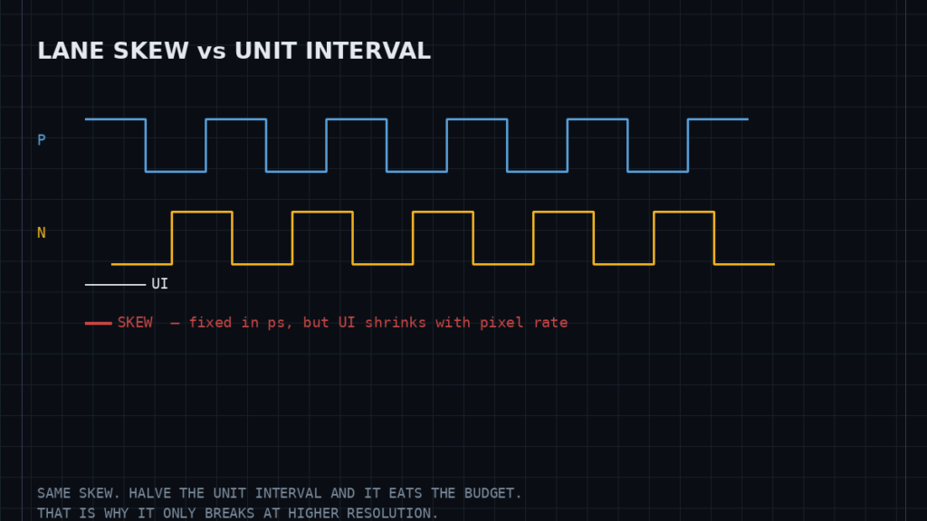
High-speed camera links fail in a way that misleads. The picture is perfect at a low resolution, degrades at a higher one, and the corruption is not random noise but structured — a band of wrong colour, a row offset, whole frames dropped. Swapping the sensor module changes nothing. Swapping the cable sometimes does.
That pattern points at the physical layer, and specifically at skew.
What skew is, and the two kinds that matter
Differential signalling carries each bit as the difference between two conductors. The receiver looks only at that difference, which is what makes it immune to noise picked up equally by both wires. That immunity assumes the two conductors are electrically identical.
Intra-pair skew is a timing difference between the two halves of a single pair. When one leg arrives late, the transition is no longer clean: part of the signal appears as a common-mode step rather than a differential one. This both radiates and eats into the receiver’s noise margin.
Inter-pair skew is a timing difference between one lane and another, or between a data lane and the clock. Interfaces such as MIPI CSI-2 running over the D-PHY physical layer are source-synchronous: the transmitter sends a clock alongside the data, and the receiver samples the data against it. If the lanes do not arrive together, the sampling point drifts away from the centre of the eye.
Why it only appears at higher resolution
This is the part that makes the fault look like a sensor problem, and it follows from one relationship.
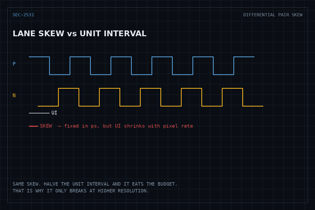
Skew is a fixed quantity in picoseconds, set by the physical path. What changes with resolution and frame rate is the unit interval — the time occupied by a single bit. Doubling the pixel rate halves the unit interval, while the skew stays exactly where it was. The same physical defect that consumed a small fraction of the timing budget at 720p can consume most of it at 1080p60.
So the link does not degrade gradually. It works, and then it does not, at whatever rate the accumulated skew crosses the receiver’s tolerance.
Where the picoseconds come from
- Trace length mismatch. The obvious one, and the easiest to design out. Signals propagate at a finite speed through the board, so a length difference is a time difference.
- Fibre weave. A PCB substrate is not homogeneous. Glass and resin have different dielectric constants, and a trace running along a glass bundle propagates at a different velocity than its partner running over resin. Two traces of identical length can therefore have different delays.
- Vias. Each via adds delay and a stub. Pairs should transition layers together, symmetrically.
- Connectors and flex cables. Usually the largest single contributor in a camera assembly, and the one most likely to change over time. A ribbon that is creased, partially seated, or of unknown quality adds both skew and loss.
- Length matching done in the wrong place. Serpentine compensation added far from the mismatch leaves a section of the pair uncoupled, which converts differential energy to common mode even though the totals now agree.
Confirming it is skew
The fastest test needs no instruments. Reduce the link rate — fewer pixels, a lower frame rate, or more lanes at a lower per-lane rate — and see whether the corruption disappears. A fault that tracks the unit interval is a timing-margin fault. A fault that persists at every rate is not.
Beyond that, the receiver usually knows more than the image shows. CSI-2 receivers maintain error counters, and on Linux those surface through the media subsystem; the camera sensor driver documentation and the V4L2 sub-device API describe how sensor and receiver drivers expose their state. Distinguishing ECC-corrected errors from CRC failures separates a link with shrinking margin from one that has already lost it.
Where an oscilloscope with sufficient bandwidth is available, the direct measurement is an eye diagram at the receiver: skew shows up as horizontal closure, loss as vertical closure. The two have different fixes, which is why it is worth telling them apart.
Fixes
- Reseat or replace the flex cable with a shorter one of specified impedance. In an assembled product this resolves the majority of cases and costs nothing to try.
- Match lengths within each pair first, then between pairs, and place the compensation adjacent to the mismatch rather than at the end of the run.
- Route pairs on a single layer where possible; when a layer change is unavoidable, keep it symmetrical for both legs.
- Reduce the per-lane rate by using more lanes. This buys margin without touching the layout.
- Use the deskew facility if the link and both endpoints support it. Higher-speed D-PHY operation provides an initial deskew sequence that lets the receiver compensate for static lane-to-lane skew; it corrects a fixed offset, not a marginal or intermittent connection.
What this fault is not
Structured corruption that scales with data rate is a physical-layer problem. It is worth ruling in before replacing sensors, because two other faults look similar from the outside: an inadequate supply to the sensor module, which produces dropouts correlated with illumination rather than resolution, and insufficient bandwidth further along the pipeline, which drops whole frames cleanly instead of tearing them. Skew corrupts the frame while delivering it — that distinction is usually enough to tell the three apart.
Specifications and references
The primary documentation for the interfaces discussed above.